Motor-driven wheel small in size and improved in ride comfort, ease of assembly and reliability

a technology of motor-driven wheels and small wheels, which is applied in the direction of electric propulsion mounting, electric devices, couplings, etc., can solve the problems of considerable axial force exerted on the motor, the difficulty of mounting the motor depending, etc., and achieve the effect of improving the ride comfort of vehicles, improving reliability, and small in siz

Inactive Publication Date: 2007-05-15
TOYOTA JIDOSHA KK
View PDF9 Cites 26 Cited by
  • Summary
  • Abstract
  • Description
  • Claims
  • Application Information

AI Technical Summary

Benefits of technology

[0008]An object of the present invention is to provide a motor-driven wheel that is small in size and improved in reliability while improving ride comfort of vehicles.
[0018]According to the present invention, the decelerator is placed closer to the outside of the vehicle, relative to the position of the hub bearing. Therefore, the space where the motor is to be mounted can readily be secured. The constant-velocity joint supports the motor swingably in the axial direction. Therefore, even if an enormous axial force is exerted on the motor, the motor-driven wheel can endure the axial force. Further, in the state where the outer race of the constant-velocity joint is supported swingably and rotatably with respect to the hub, the lubricant for the constant-velocity joint and the decelerator can appropriately be enclosed hermetically.
[0019]Furthermore, while the bearing suppresses an axial movement of the inner race of the constant-velocity joint, the wheel can smoothly be rotated. The constant-velocity joint can be reduced in size and improved in ease of installation. Moreover, the motor output shaft can be prevented from coming off the outer race to protect the spline-fit portion of the motor output shaft against, for example, entry of foreign matters and rust.

Problems solved by technology

However, if the motor is mounted to serve as the dynamic damper as mentioned above, it is necessary to avoid interference between the motor and peripheral components since the motor vibrates, resulting in a problem of possible difficulty in mounting the motor depending on the position of the decelerator.
Further, when the vehicle corners, a considerably great axial force is exerted on the motor.

Method used


Image

  • Motor-driven wheel small in size and improved in ride comfort, ease of assembly and reliability
  • Motor-driven wheel small in size and improved in ride comfort, ease of assembly and reliability
  • Motor-driven wheel small in size and improved in ride comfort, ease of assembly and reliability

Examples


Embodiment Construction

[0034]An embodiment of the present invention is hereinafter described in detail with reference to the drawings. In the drawings, like components are denoted by like reference characters and a description thereof is not repeated.

[0035]Entire Structure of Motor-Driven Wheel

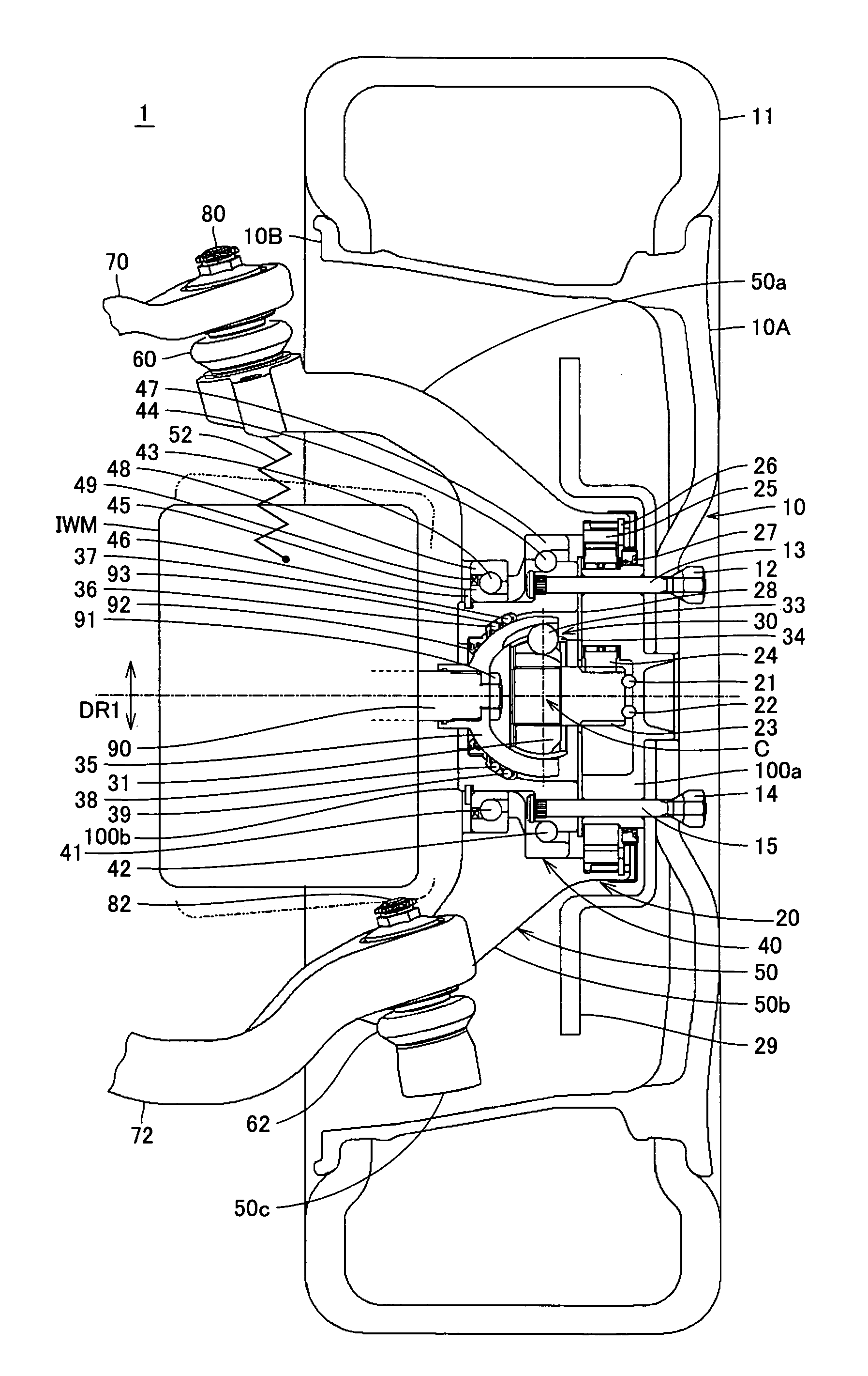
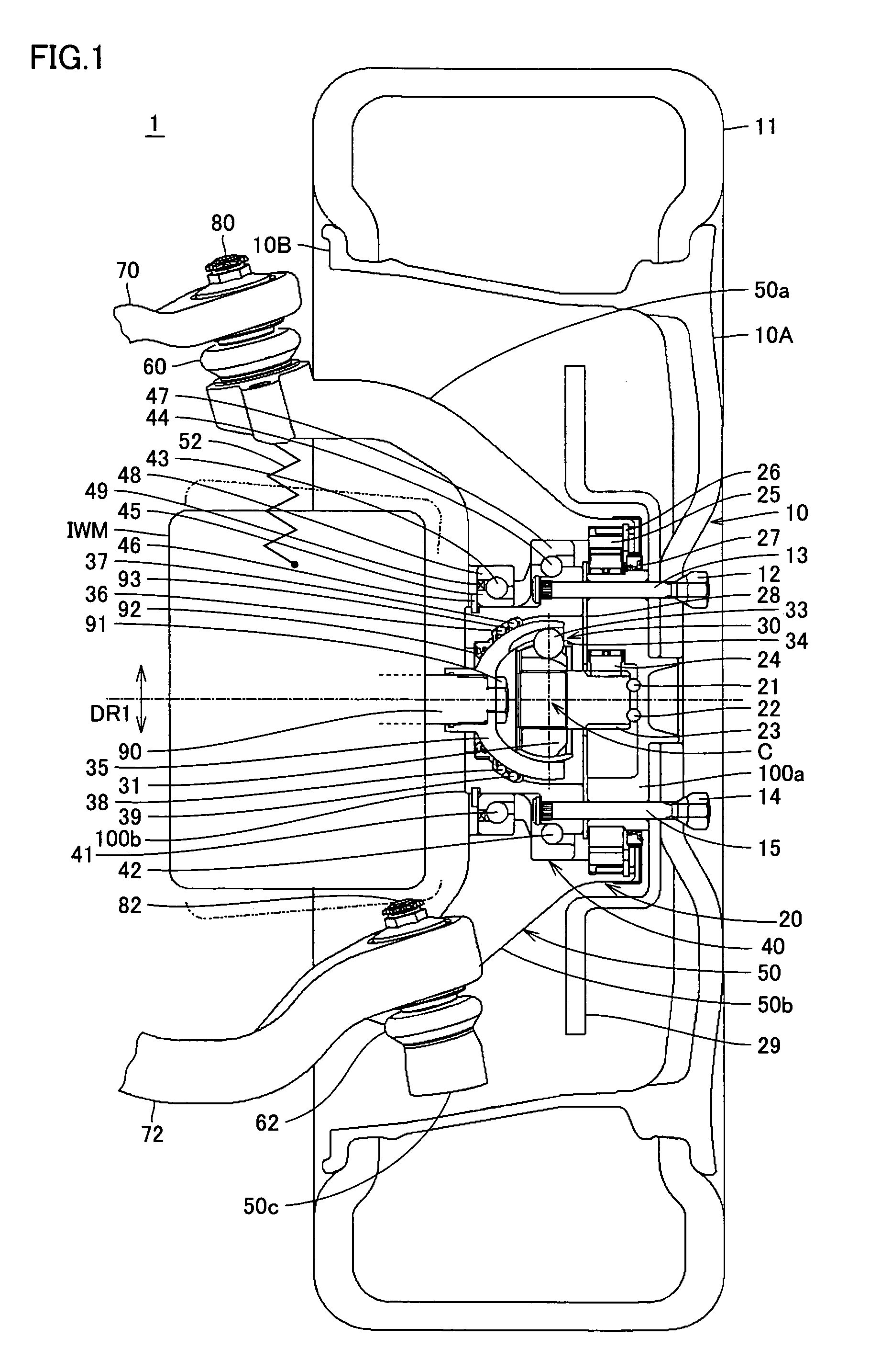
[0036]FIG. 1 shows an entire structure of a motor-driven wheel according to the embodiment of the present invention.

[0037]Referring to FIG. 1, motor-driven wheel 1 includes a wheel disc 10, a wheel hub 100b, a decelerator 20, a knuckle 50, a hub bearing 40, a constant-velocity joint 30, an in-wheel motor IWM, and a spring 52. Wheel hub 100b is connected to a planetary carrier 100a in decelerator 20 with bolts 13, 15 and nuts 12, 14 to form a so-called wheel hub. Here, for convenience of description, wheel hub 100b is called wheel hub.

[0038]Motor-driven wheel 1 is supported by a suspension arm that is a wheel support unit. The suspension arm includes an upper arm 70 and a lower arm 72. Upper arm 70 and an upper knuck...


PUM


Abstract

A motor-driven wheel includes a wheel disc, a wheel hub, a decelerator, a knuckle, a hub bearing, a constant-velocity joint, an in-wheel motor, and a spring. Since the decelerator is placed closer to the outside of the vehicle relative to the hub bearing, the space where the in-wheel motor is to be mounted can readily be secured. Further, balls are arranged along a spherical external surface of an outer race and the outer race is supported swingably in the axial direction. Thus, even when a great axial force is exerted, the axial force can be endured. The outer race can be supported swingably and rotatably with respect to the wheel hub.

Description

[0001]This nonprovisional application is based on Japanese Patent Application No. 2004-147910 filed with the Japan Patent Office on May 18, 2004, the entire contents of which are hereby incorporated by reference.BACKGROUND OF THE INVENTION[0002]1. Field of the Invention[0003]The present invention relates to a motor-driven wheel improving ride comfort of vehicles.[0004]2. Description of the Background Art[0005]An in-wheel motor drive unit that uses a motor as the mass of a damper and that supports the motor by a motor suspension is known (Document 1: International Patent Publication No. WO02 / 083446A1, Document 2: Go Nagaya et al., “Development of an In-Wheel Motor with Advanced Dynamic-Damper Mechanism (20025544)”, Proceedings of 2002 JSAE Autumn Convention, No. 83-02, The Society of Automotive Engineers of Japan, Nov. 26, 2002, pp. 9–12). The motor is coupled to a wheel of a wheel and tire unit (hereinafter referred to as wheel unit) to rotate the wheel unit. The motor suspension su...

Claims


Application Information

Patent Timeline
Patent Type & Authority Patents(United States)
IPC IPC(8): B60K1/00B60B35/14B60G13/16B60B35/18B60K7/00F16D3/20F16D3/2237F16D3/2245
CPCB60K7/00B60K17/046B60K2007/0053B60K2007/0061B60L2220/46
Inventor KAKINAMI, TAKUMAYAMAMOTO, TAKEOYOGO, SHIGEKAZU
Owner TOYOTA JIDOSHA KK
Why Eureka
Try Eureka