
Prosthesis locking assembly

a technology of locking assembly and protruding axle, which is applied in the direction of prosthesis, rod connection, coupling, etc., can solve the problems of hard socket connection, affecting the use of prosthesis, and difficult for users of prosthesis to release the liner from the hard socket and the components connecting to the foo

Active Publication Date: 2007-05-15
KAUPTHING BANK
View PDF13 Cites 78 Cited by
  • Summary
  • Abstract
  • Description
  • Claims
  • Application Information

AI Technical Summary

Benefits of technology

[0006]The present invention provides a prosthetic lock assembly that may be used in combination with a prosthesis and which eliminates problems of prior existing lock devices.
[0009]By providing the groove and ball bearing arrangement, the centering axle is able to slide within the lock body in a smoother fashion. The improved operation of the centering axle reduces the amount of force required by a user of the prosthetic lock assembly and facilitates the release of an attachment pin disposed within the lock body.

Problems solved by technology

A problem inherent in the conventional locking assemblies is that the centering axle has a tendency to bind with the pinion gear upon wear of the prosthesis and due to the forces applied to the locking assembly by the weight of the user.
Such binding of the centering axle with the attachment, in turn, makes it difficult for a user of the prosthesis to release the liner from the hard socket and components connecting to the foot.

Method used


Image

  • Prosthesis locking assembly
  • Prosthesis locking assembly
  • Prosthesis locking assembly

Examples


Embodiment Construction

[0020]A better understanding of different embodiments of the invention may be had from the following description read in conjunction with the accompanying drawings in which like reference characters refer to like elements.

[0021]While the disclosure is susceptible to various modifications and alternative constructions, certain illustrative embodiments thereof are shown in the drawings and will be described below in detail. It should be understood, however, that there is no intention to limit the disclosure to the specific embodiments disclosed, but on the contrary, the intention is to cover all modifications, alternative constructions, and equivalents falling within the spirit and scope of the disclosure as defined by the appended claims.

[0022]It will be understood that, unless a term is expressly defined in this patent to possess a described meaning, there is no intent to limit the meaning of such term, either expressly or indirectly, beyond its plain or ordinary meaning.

[0023]FIG. ...


PUM


Abstract

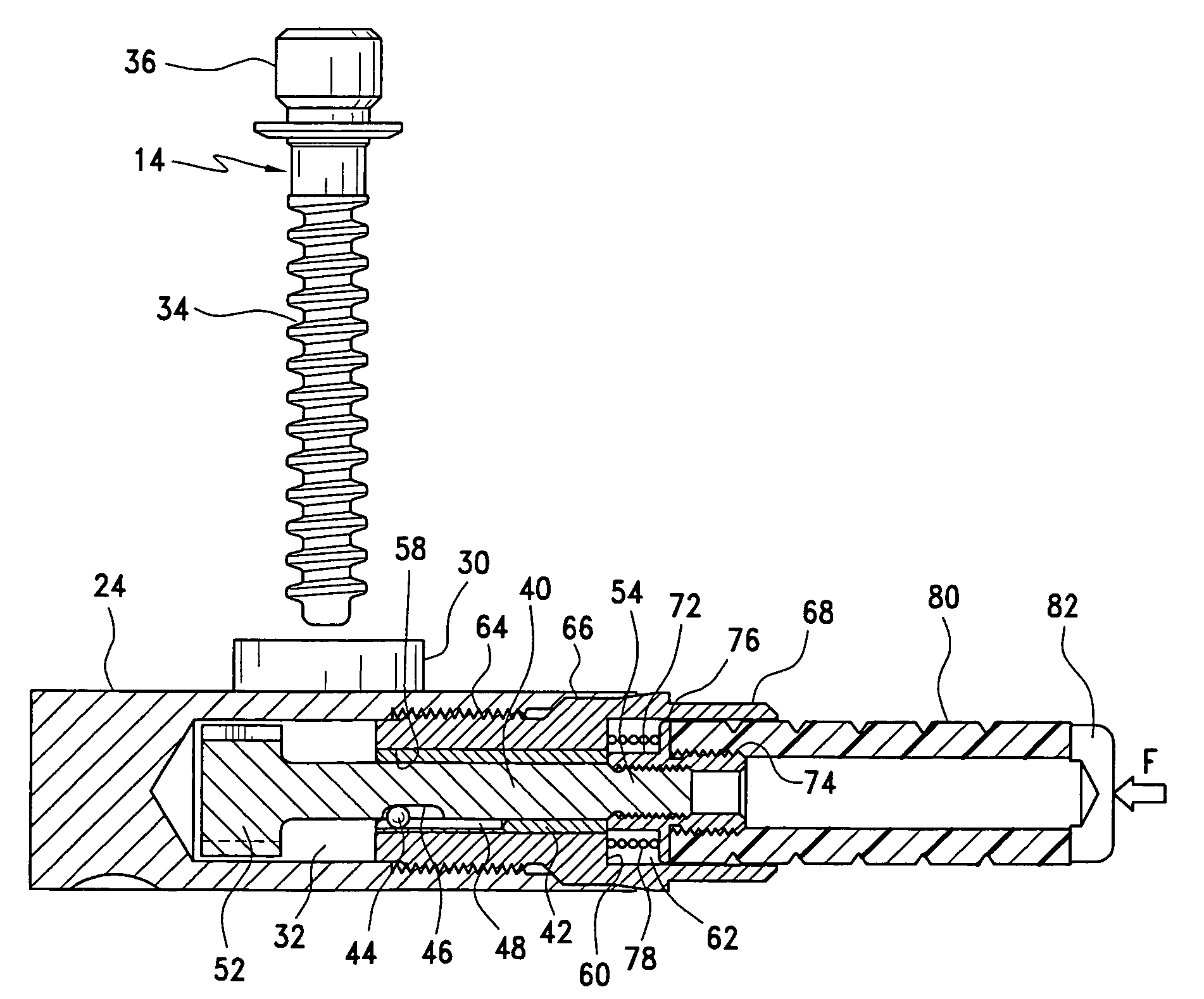
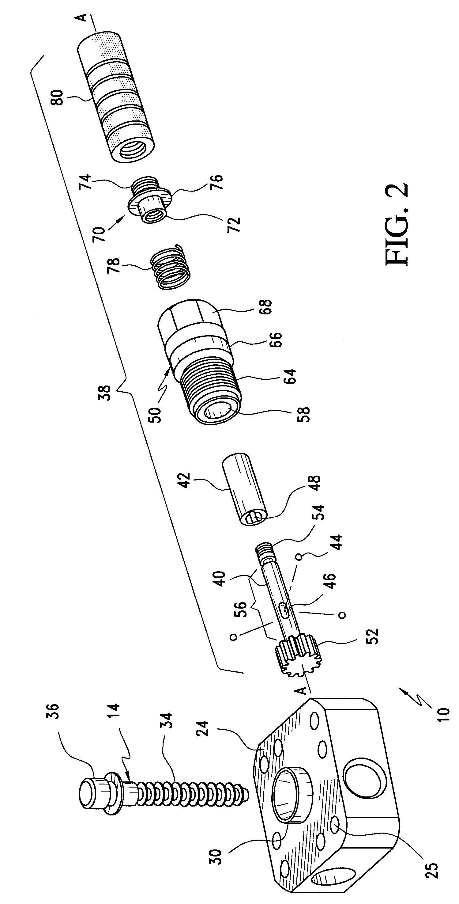
A locking mechanism includes a centering axle having an engaging member defined at one end thereof, a sleeve encompassing a portion of the centering axle, and a clutch device that securely receives the sleeve and permits rotation of the centering axle and the sleeve in only one direction. The centering axle defines a plurality of equally spaced grooves, and the sleeve defines a plurality of equally spaced grooves corresponding to the grooves of the centering axle in an opposed manner. Each pair of opposed grooves of the centering axle and sleeve define a narrow passageway that accommodates a ball bearing that is slidable along the longitudinal axis of the centering axle and between the sleeve and centering axle. The ball bearing in each passageway permits longitudinal movement of the centering axle relative to the sleeve and prohibits rotation of the centering axle relative to the sleeve.

Description

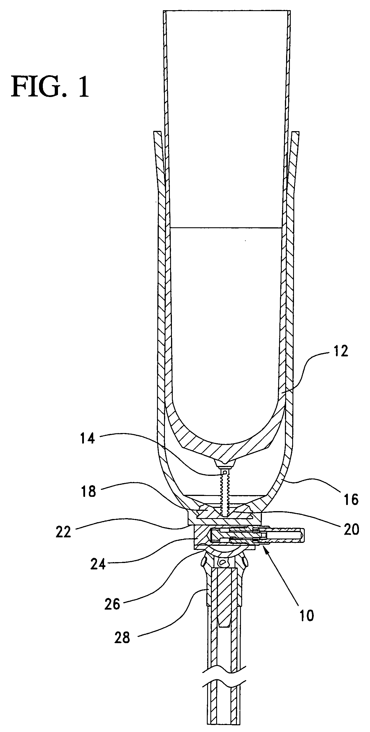
BACKGROUND OF THE INVENTION[0001]This disclosure is directed to a locking assembly, and in particular to a locking assembly including a locking mechanism for use in a prosthesis.[0002]A prosthesis is a replacement limb comprised of a plurality of parts. The first component is a liner which is donned by a residual limb. The liner acts as a protective interface between a hard, weight bearing socket and the skin of the residual limb. Once the liner donned on the limb, the residual limb is received by the hard socket. The socket is made to specifically fit the residual limb. The hard socket for a transfemoral prosthesis (above-knee) has a component such as a knee joint connected to it. Below that is an aluminum or carbon fiber tube to which a foot module is connected. A transtibial prosthesis (below-knee) has the foot connected either directly to the hard socket or via a tube, depending on the amputee's height and the length of the residual limb.[0003]Typically, an attachment pin is con...

Claims


Application Information

Patent Timeline
Patent Type & Authority Patents(United States)
IPC IPC(8): F16B21/00A61F2/60A61F2/76A61F2/78A61F2/80B60B27/00
CPCA61F2/60A61F2/76A61F2/80A61F2/7812A61F2002/7875Y10T403/593Y10T403/598Y10T403/32451Y10T403/591Y10T403/69Y10T403/599Y10T403/59Y10T403/32434
Inventor INGIMARSSON, GUDNI
Owner KAUPTHING BANK
Learn More