Countering laser shock peening induced airfoil twist using shot peening

a technology of laser shock peening and airfoil twist, which is applied in the direction of machines/engines, climate sustainability, waterborne vessels, etc., can solve the problems of substantial aerodynamic problems and alter the twist of the airfoil

Inactive Publication Date: 2007-05-15
GENERAL ELECTRIC CO
View PDF16 Cites 30 Cited by
  • Summary
  • Abstract
  • Description
  • Claims
  • Application Information

AI Technical Summary

Problems solved by technology

There are associated distortions of thin compressor and turbine blades that alter the profile of the blade and, therefore, may cause substantial aerodynamic problems.
These associated distortions include an alteration of twist of the airfoil of the blades.

Method used


Image

  • Countering laser shock peening induced airfoil twist using shot peening
  • Countering laser shock peening induced airfoil twist using shot peening
  • Countering laser shock peening induced airfoil twist using shot peening

Examples


Embodiment Construction

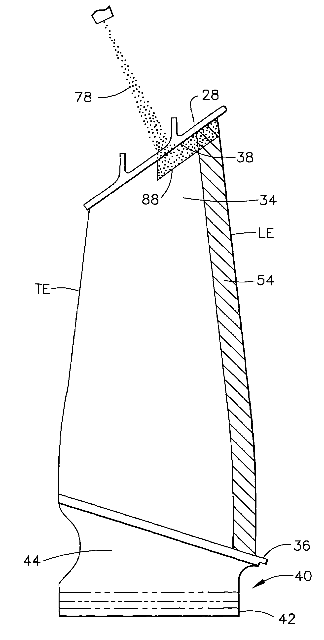
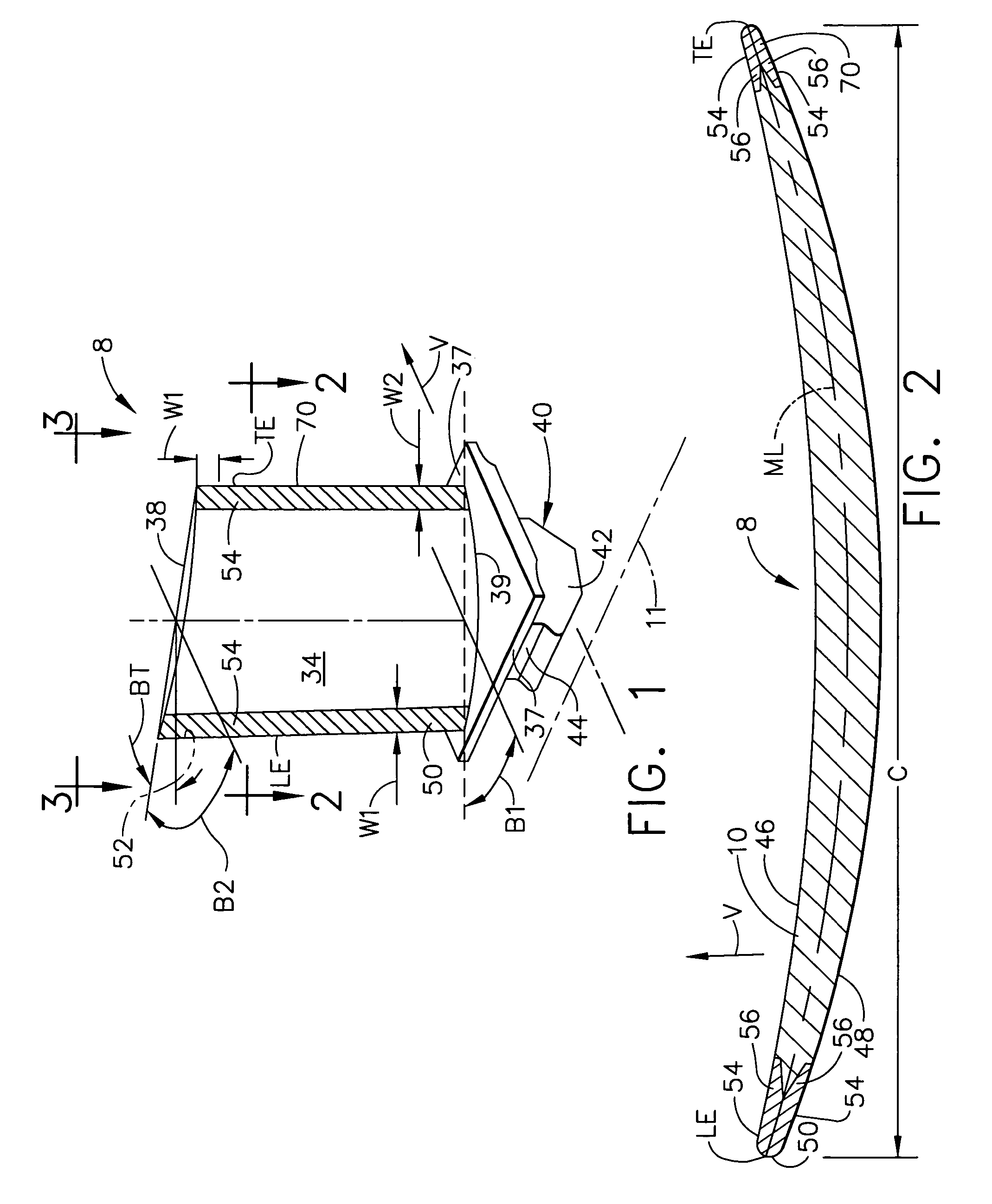
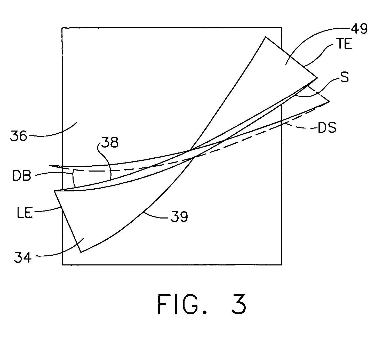
[0015]Illustrated in FIGS. 1, 2, and 3 is a gas turbine engine blade 8 having a thin airfoil 34 made of a Titanium or Nickel based alloy extending radially outwardly from a blade platform 36 to a blade tip 38. The blade 8 is representative of a compressor or turbine blade with a laser shock peened surface 54 on a metallic substrate 10 of the airfoil 34 along a leading edge LE of the airfoil 34. The blade 8 includes a root section 40 extending radially inward from the platform 36 to a radially inward end 37 of the root section 40. At the radially inward end 37 of the root section 40 is a blade root 42 which is connected to the platform 36 by a blade shank 44. The blade root 42 has a root centerline 45 which is generally parallel to the platform 36, side edges 35 of the platform 36, and the blade shank 44. The roots 42 are shaped to slide into retention slots on a compressor or turbine rotor of the engine.

[0016]The airfoil 34 extends in the chordwise direction between the leading edge...


PUM

PropertyMeasurementUnit
areaaaaaaaaaaa
pressureaaaaaaaaaa
compressive residual stressesaaaaaaaaaa

Abstract

A gas turbine engine blade is laser shock peened by laser shock peening a thin airfoil of the blade, forming a laser shock induced twist in the airfoil, and shot peening a portion of the airfoil to counter the laser shock induced twist in the airfoil. The shot peening may be performed before or after the laser shock peening. The shot peening may be applied over a laser shock peened surface formed by the laser shock peening. The shot peening may be performed asymmetrically on asymmetrically shot peened pressure and suction side areas of pressure and suction sides, respectively, of the airfoil. A shot peened patch near a blade tip may be formed on one of pressure and suction sides of the airfoil wherein the airfoil extends radially outwardly from a blade platform to the blade tip of the blade.

Description

BACKGROUND OF THE INVENTION[0001]This invention relates to gas turbine engine rotor blades with leading and trailing edges having localized compressive residual stresses imparted by laser shock peening and, more particularly, to techniques for countering laser shock peening induced twist of the airfoils of these blades.[0002]Laser shock peening (LSP) or laser shock processing, as it is also referred to, is a process for producing a region of deep compressive residual stresses imparted by laser shock peening a surface area of an article. Laser shock peening typically uses one or more radiation pulses from high and low power pulsed lasers to produce an intense shockwave at the surface of an article similar to methods disclosed in U.S. Pat. No. 3,850,698 entitled “Altering Material Properties”; U.S. Pat. No. 4,401,477 entitled “Laser Shock Processing”; and U.S. Pat. No. 5,131,957 entitled “Material Properties”. Laser shock peening, as understood in the art and as used herein, means uti...

Claims


Application Information

Patent Timeline
Patent Type & Authority Patents(United States)
IPC IPC(8): F01D5/14
CPCB24C1/10F01D5/286Y10T29/4932Y02T50/673Y02T50/60
Inventor ROCKSTROH, TODD JAYBARBE, ROGER OWENMANNAVA, SEETHA RAMAIAH
Owner GENERAL ELECTRIC CO
Why Eureka
Try Eureka