Method and apparatus for containing and suppressing explosive detonations

a technology of explosive detonation and transportable equipment, applied in the direction of blasting, etc., can solve the problems of large space occupation, noise, dust, disturbance and contamination of the environment, and uncontrolled use of explosives in this way, and achieve the effect of reducing the risk of equipment and personnel, and reducing the risk of explosion

Active Publication Date: 2017-12-26
DONOVAN JOHN L
View PDF20 Cites 0 Cited by
  • Summary
  • Abstract
  • Description
  • Claims
  • Application Information

AI Technical Summary

Benefits of technology

[0011]The chamber itself is an elongate cylindrical steel containment vessel having an access door for introducing workpieces and a vent door for discharging explosion products. Both doors extend convexly into the vessel to facilitate the dissipation of explosion shock waves. Orificed vent pipes penetrate the vessel walls to controllably release explosion products into one or more exhaust manifolds.

Problems solved by technology

This process involves placing an explosive-covered hardenable metal workpiece in an open field, or at the bottom of an open pit such an abandoned gravel pit, and setting off the explosion in the open air, which resulted in objectionable noise, dust, disturbance and contamination of the environment.
In addition, the uncontrolled use of explosives in this way required great amounts of space, posed substantial danger to equipment and personnel, and had the undesirable effect of demolishing the ignition leads, the work piece support surface, and virtually everything else within the immediate vicinity of the explosion.

Method used


Image

  • Method and apparatus for containing and suppressing explosive detonations
  • Method and apparatus for containing and suppressing explosive detonations
  • Method and apparatus for containing and suppressing explosive detonations

Examples


Embodiment Construction

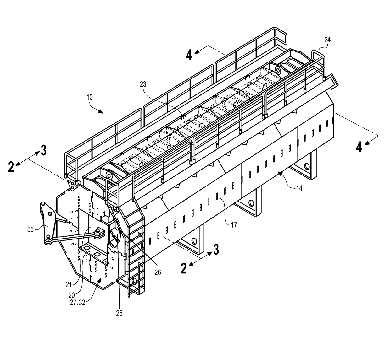
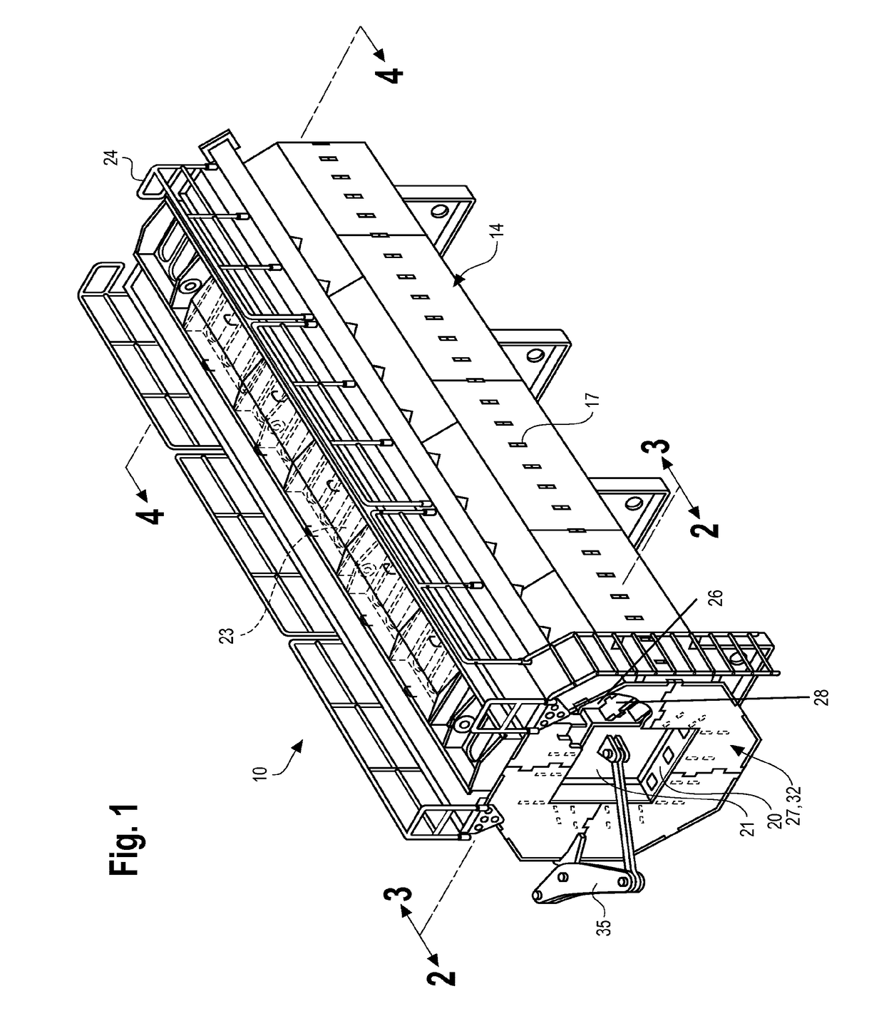
[0021]Turning to FIG. 1, this isometric perspective view shows the assembled chamber ready for the introduction of an explosive or explosive-covered workpiece. In use, it would be bolted down and supported by a reinforced concrete footing or foundation (not shown) in a conventional manner.

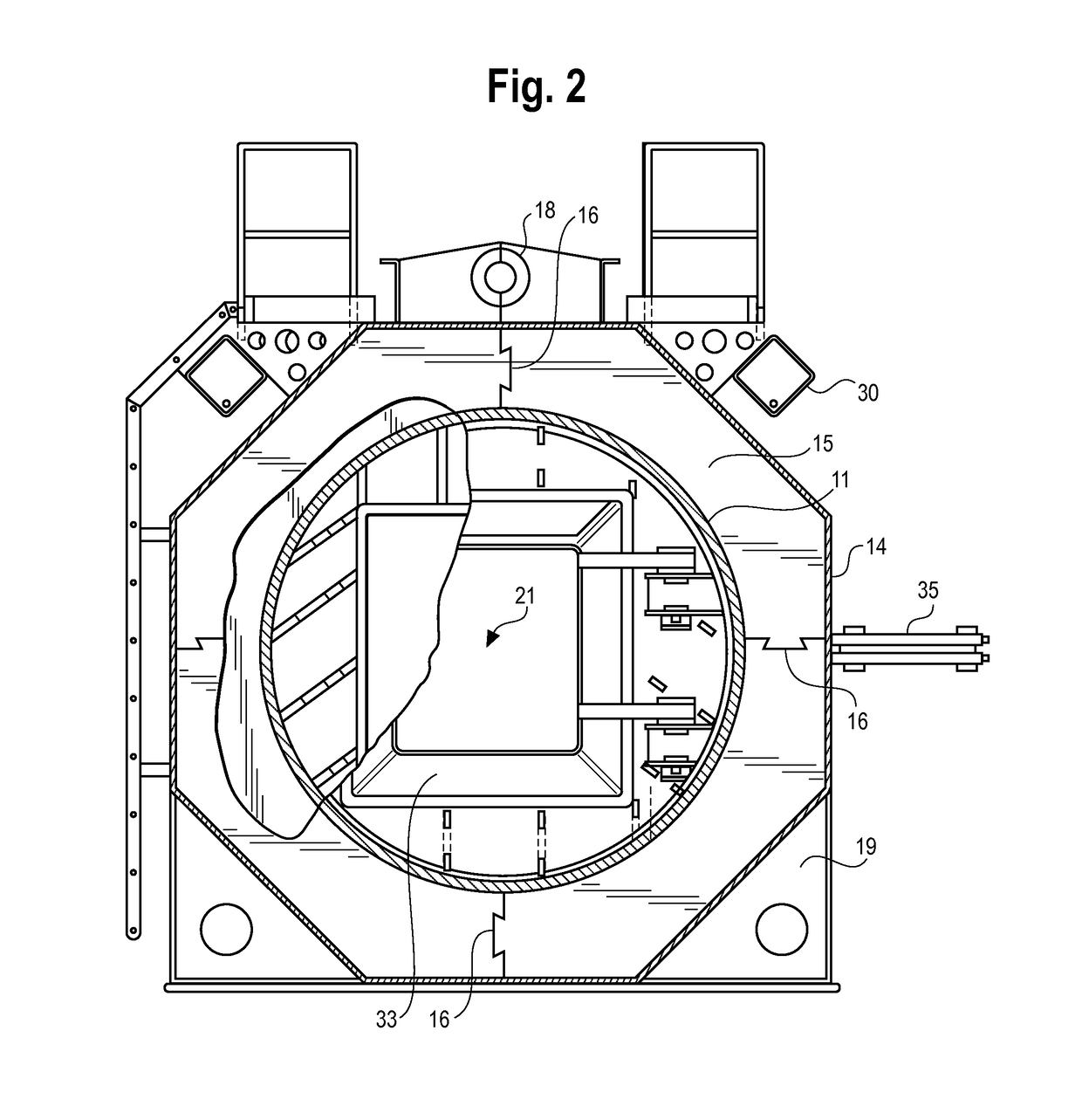
[0022]As best shown in the remaining figures, the chamber assembly 10 comprises a cylindrical inner containment vessel 11 having an inward-swinging charging door 21 and a hemispherical end closure 12. The inner vessel 11 is preferably fabricated of sheet steel using conventional welding techniques. The vessel 11 is supported and strengthened by multiple equally-spaced parallel octagonal stiffener plates or ribs 13. In the illustrated embodiment, the inner containment vessel 11 is 34 feet long, and is supported by 25 ribs 13 which are equally spaced at 16 inch intervals. The assembled inner vessel 11 and surrounding ribs 13 are enclosed by an external enclosure formed of welded sheet steel skin plat...


PUM


Abstract

A transportable explosion chamber and method of operation for containing, controlling and suppressing explosive detonations, including the explosion surface hardening of impact-hardenable rail components. The apparatus comprises an elongate cylindrical steel containment vessel having an access door for introducing workpieces and a vent door for discharging explosion products. Both doors extend convexly into the vessel to facilitate the dissipation of explosion shock waves. Orificed vent pipes penetrate the vessel walls to controllably release explosion products into one or more exhaust manifolds. The vessel is surrounded and enclosed by steel skins supported by spaced octagonal steel support ribs fabricated by welding from interlocking elements. The hollows formed between the containment vessel and steel skins are filled with granular shock-damping silica sand which is introduced through filler openings at the top of the apparatus. To lighten the apparatus for transport, the shock-damping material may be drained through dump valves beneath the apparatus.

Description

FIELD OF THE INVENTION[0001]This invention relates to a transportable apparatus and method of operation for containing, controlling and suppressing explosive detonations, including the explosion surface hardening of impact-hardenable rail componentsBACKGROUND OF THE INVENTION[0002]Explosives have many useful industrial applications. These include surface hardening of austenitic manganese alloy steels, surface deposition coating, welding of metallic components, compression molding of components from powders and granular media, and disposal of unwanted explosive or toxic materials, among others.[0003]The prior art reflects many attempts to contain the explosion process for the suppression of noise, shock and noxious polluting explosion products. Many of these attempts are described in this inventor's prior patents, including U.S. Pat. No. 5,613,453 (now U.S. Pat. No. RE 36,912), which disclosure is incorporated herein by reference.[0004]All of the above-mentioned prior art devices rep...

Claims


Application Information

Patent Timeline
Patent Type & Authority Patents(United States)
IPC IPC(8): F42D3/00F42D5/045
CPCF42D5/045F42D3/00
Inventor DONOVAN, JOHN L
Owner DONOVAN JOHN L
Why Eureka
Try Eureka