Tennis racket

a tennis racket and tennis technology, applied in the field of tennis rackets, can solve the problems of increasing the moment of inertia in the center direction, deteriorating operability and face stability, and increasing the difficulty of the tennis racket rotating on the axis, so as to improve the moment of inertia, facilitate the rotation, and facilitate the operation

Inactive Publication Date: 2007-05-15
DUNLOP SPORTS CO LTD
View PDF8 Cites 15 Cited by
  • Summary
  • Abstract
  • Description
  • Claims
  • Application Information

AI Technical Summary

Benefits of technology

[0017]The present invention has been made in view the above-described problem. Therefore, it is an object of the present invention to provide a tennis racket that has a high vibration-damping performance and a high rebound performance without making the tennis racket heavy, and has a high degree of controllability due to an improvement in face stability.

Problems solved by technology

Therefore the moment of inertia in the center direction increases and the tennis racket has difficulty in its rotation on its axis.
Thus the rebound performance of the racket frame is enhanced but its operability and face stability deteriorate.

Method used


Image

  • Tennis racket
  • Tennis racket
  • Tennis racket

Examples


example 1

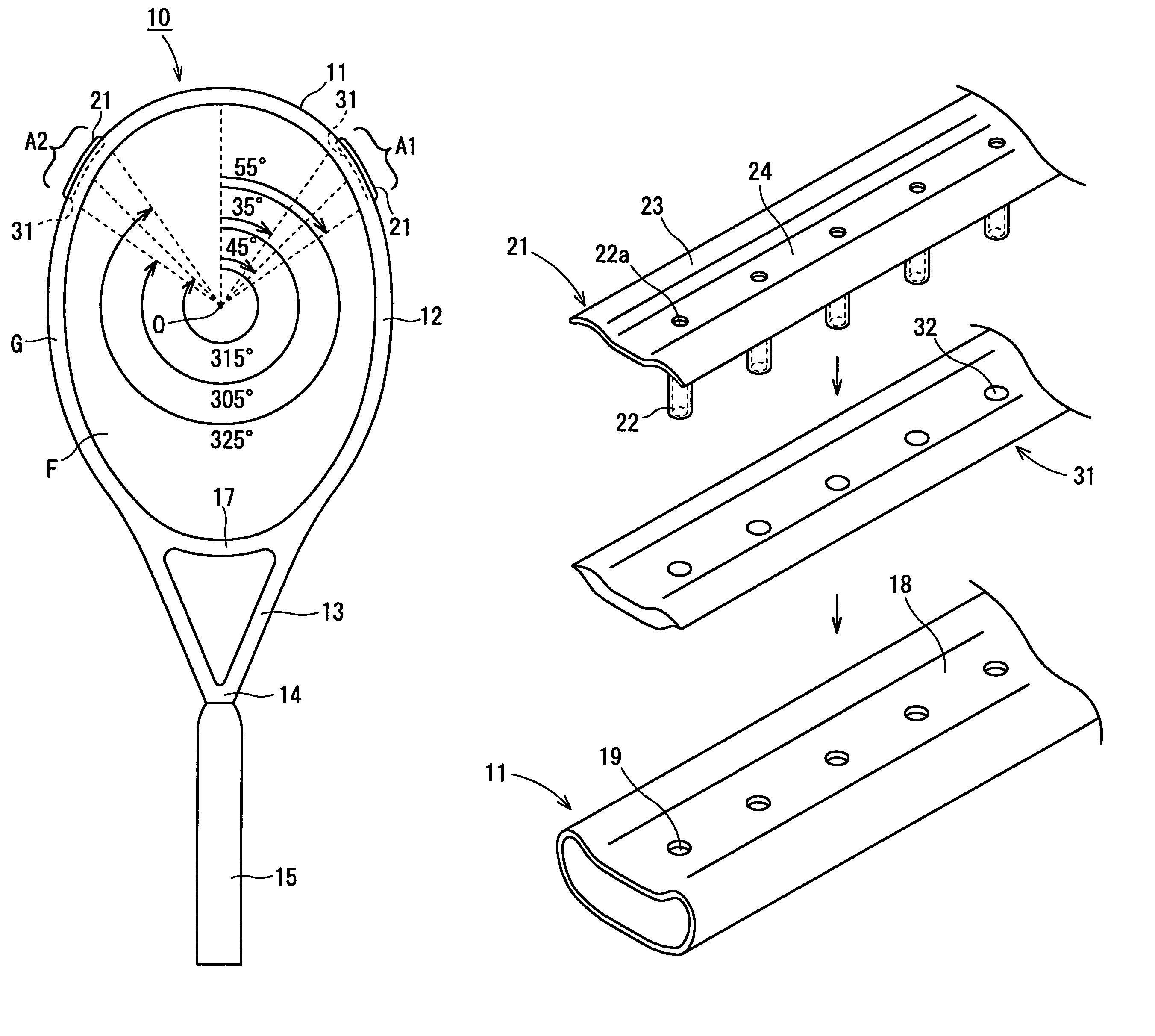
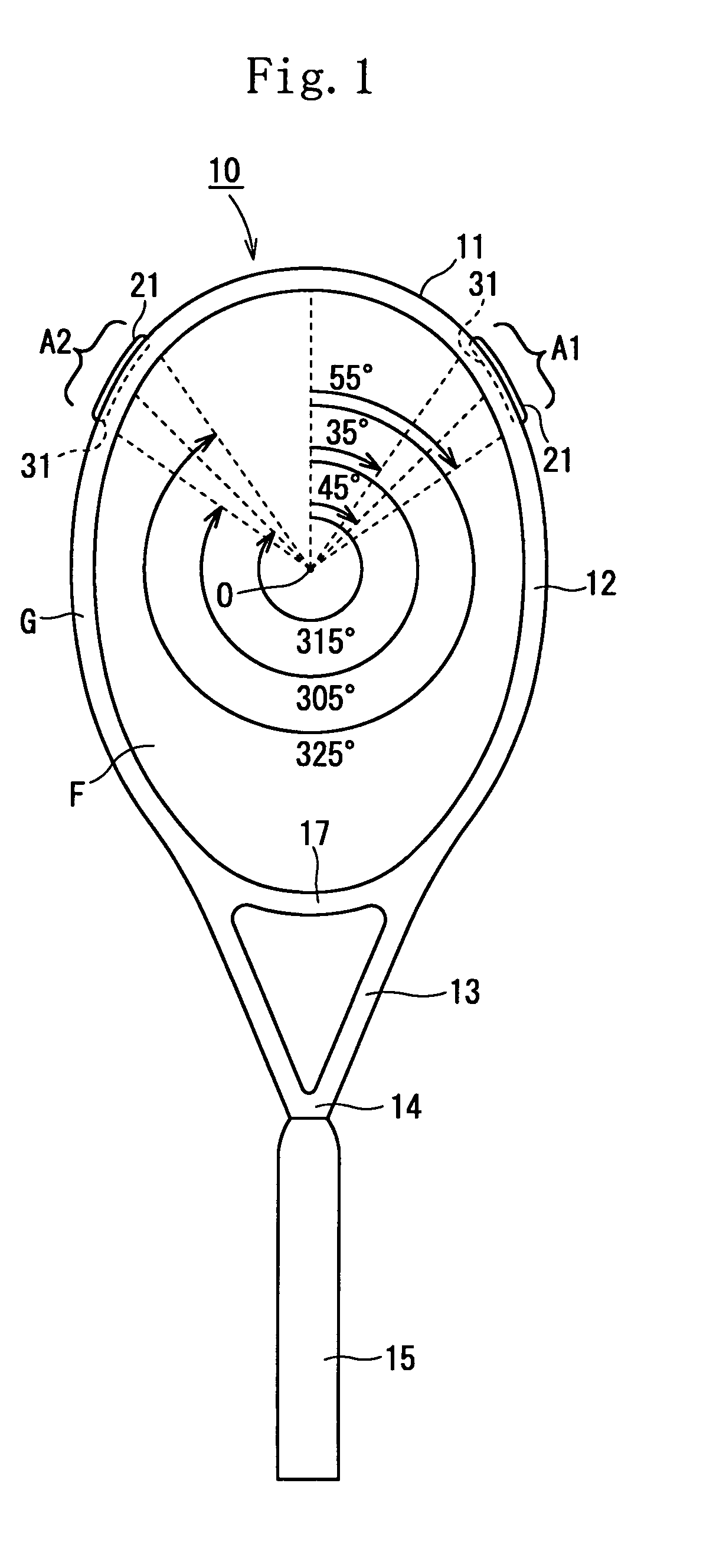
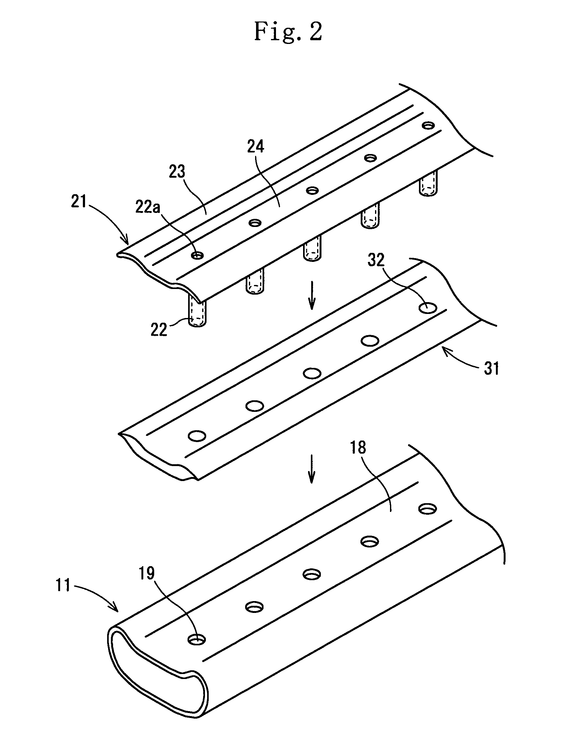
[0106]The thickness, weight, and position of the string protection member 21 and the material, complex elastic modulus, thickness, weight, and position of the viscoelastic member 31 were all identical to those of the first embodiment. That is, the viscoelastic member 31 was formed by molding a vulcanized rubber composition consisting of 100 parts by weight of styrene-butadiene rubber (SBR), 1.5 parts by weight of sulfur, and 40 parts by weight of carbon black. The viscoelastic member 31 had a thickness of 3 mm and a weight of 3 g. The complex elastic modulus of the viscoelastic member 31 measured in the above-described condition was 3.86E+08 dyn / cm2. The string protection member 21 had a thickness of 1 mm and a weight of 2 g. One string protection member 21 and one viscoelastic member 31 were disposed in each of the above-described ranges A1 and A2. The tennis racket 10 had a weight of 240 g.

[0107]The moment Is of inertia of the tennis racket in the swing direction was set to 460,00...

example 2

[0108]The thickness, weight, and position of the string protection member 21 and the material, complex elastic modulus, thickness, weight, and position of the viscoelastic member 31 were all identical to those of the second embodiment (FIG. 5). That is, the example 2 is different from the example 1 in that one string protection member 21 and one viscoelastic member 31 were disposed in each of the above-described ranges B1 and B2. The tennis racket 10 had a weight of 239 g. The moment Is of inertia of the tennis racket in the swing direction when strings were not mounted on the racket frame was set to 456,000 g / cm2. The moment Ic of inertia thereof in the center direction when strings were not mounted on the racket frame was set to 17,200 g / cm2 (the ratio of the moment Is of inertia to the moment Ic of inertia: about 27).

example 3

[0109]The thickness, weight, and position of the string protection member 21 and the material, complex elastic modulus, thickness, weight, and position of the viscoelastic member 31 were all identical to those of the third embodiment (FIG. 6). That is, the example 3 is different from the example 1 in that one string protection member 21 and one viscoelastic member 31 were disposed in each of the above-described ranges C1 and C2. The tennis racket 10 had a weight of 240 g. The moment Is of inertia of the tennis racket in the swing direction when strings were not mounted on the racket frame was set to 450,000 g / cm2. The moment Ic of inertia thereof in the center direction when strings were not mounted on the racket frame was set to 16,400 g / cm2 (the ratio of the moment Is of inertia to the moment Ic of inertia: about 27).


PUM


Abstract

A tennis racket having a racket frame defining a ball-hitting face, wherein if the upper part of the ball-hitting face is set as a 0-degree position, a string protection member is mounted on at least one portion of a head part of the racket frame in a range from a clockwise 45-degree position to a clockwise 135-degree position and in a range from a clockwise 225-degree position to a clockwise 315-degree position by interposing a viscoelastic member between the string protection member and the racket frame. The moment (Is) of inertia of the tennis racket in a swing direction is set to not less than 450,000 g / cm2 nor more than 490,000 g / cm2, when strings are not tensionally mounted thereon. The moment (Ic) of inertia of the tennis racket in a center direction is set to not less than 15,000 g / cm2 nor more than 19,000 g / cm2, when the strings are not tensionally mounted thereon.

Description

[0001]This Nonprovisional application claims priority under 35 U.S.C. § 119(a) on Patent Application No(s). 2004-055463 filed in Japan on Feb. 27, 2004, the entire contents of which are hereby incorporated by reference.BACKGROUND OF THE INVENTION[0002]The present invention relates to a tennis racket. More particularly, the present invention relates to a lightweight tennis racket for regulation-ball tennis having improved restitution performance, ball controllability, and vibration-damping performance.[0003]The so-called “thick racket” which is thick in the out-of-plane direction of the racket frame is commercially available. Female and senior tennis players require the “thick racket” because they desire the tennis racket to have highs ball rebound performance, even though they hit the ball with a small amount of power. That is, they demand a tennis racket that is light in weight and has a high, ball rebound performance. Therefore a fiber reinforced resin is mainly used as the materi...

Claims


Application Information

Patent Timeline
Patent Type & Authority Patents(United States)
IPC IPC(8): A63B49/02A63B60/02A63B49/00A63B49/022A63B49/14A63B51/00A63B51/10A63B60/54A63B102/02
CPCA63B49/002A63B51/10A63B49/022
Inventor TAKEUCHI, HIROYUKIASHINO, TAKESHI
Owner DUNLOP SPORTS CO LTD
Why Eureka
Try Eureka