Catalytic reactor and process

a catalyst and reactor technology, applied in the field of catalyst reactor and process, can solve problems such as decreased activity, and achieve the effect of enhancing heat transfer and catalyst surface area

Active Publication Date: 2007-05-15
COMPACTGTL
View PDF30 Cites 8 Cited by
  • Summary
  • Abstract
  • Description
  • Claims
  • Application Information

AI Technical Summary

Benefits of technology

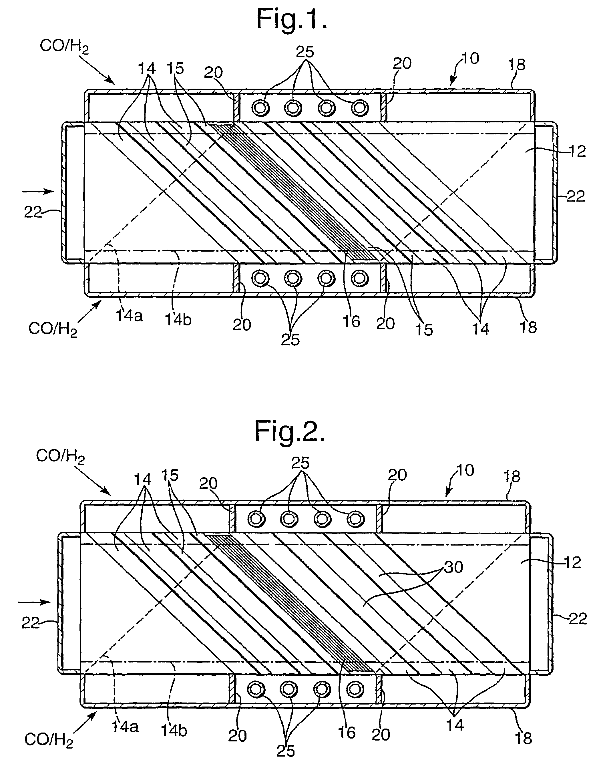
[0007]The invention also provides an apparatus for performing such a Fischer-Tropsch synthesis. This may be a compact catalytic reactor unit incorporating headers that connect successive flow channels, the headers enclosing means to condense water vapour and to remove condensed liquids from the header. The catalytic reactor unit preferably comprises a plurality of metal sheets arranged as a stack and bonded together to define channels for the Fischer-Tropsch synthesis alternating with channels for a heat exchange fluid. Preferably the temperature in the synthesis channels is above 190° C., for example 200° C. Corrugated or dimpled foils, metal meshes, or corrugated or pleated metal felt sheets may be used as the substrate of the catalyst structure within the flow channels to enhance heat transfer and catalyst surface area.
[0008]It will be appreciated that the materials of which the reactor are made are subjected to a corrosive atmosphere in use. The reactor may be made of a metal such as an aluminium-bearing ferritic steel, for example it might comprise iron with 15% chromium, 4% aluminium, and 0.3% yttrium (eg Fecralloy (™)). When this metal is heated in air it forms an adherent oxide coating of alumina which protects the alloy against further oxidation; this oxide layer also protects the alloy against corrosion. Where this metal is used as a catalyst substrate, and is coated with a ceramic layer into which a catalyst material is incorporated, the alumina oxide layer on the metal is believed to bind with the oxide coating, so ensuring the catalytic material adheres to the metal substrate. Other stainless steels may also be used. The sheets defining the channels may alternatively be of aluminium.

Problems solved by technology

A known catalyst for the Fischer-Tropsch synthesis utilises small particles of cobalt on a ceramic support, but it has been found that this catalyst can suffer oxidation or an irreversible reaction with the ceramic support in the presence of water vapour, with a resultant decrease in activity.

Method used


Image

  • Catalytic reactor and process

Examples


Embodiment Construction

[0012]The invention relates to Fischer-Tropsch synthesis, which may form part of a process for converting methane to longer chain hydrocarbons. Fischer-Tropsch synthesis is a reaction between carbon monoxide and hydrogen, and this gas mixture may for example be generated by steam / methane reforming. In Fischer-Tropsch synthesis the gases react to generate a longer chain hydrocarbon, that is to say:

nCO+2nH2→(CH2))n+nH2O

which is an exothermic reaction, occurring at an elevated temperature, typically between 190 and 350° C., for example 210° C., and an elevated pressure typically between 2 MPa and 4 MPa, for example 2.5 MPa, in the presence of a catalyst such as iron, cobalt or fused magnetite, with a promoter. The exact nature of the organic compounds formed by the reaction depends on the temperature, the pressure, and the catalyst, as well as the ratio of carbon monoxide to hydrogen.

[0013]A preferred catalyst comprises a coating of gamma-alumina of specific surface area 140–450 m2 / g w...


PUM

PropertyMeasurementUnit
pressureaaaaaaaaaa
temperatureaaaaaaaaaa
pressureaaaaaaaaaa

Abstract

Fischer-Tropsch synthesis is performed using a compact catalytic reactor unit (10) defining channels in which is a gas-permeable catalyst structure (16), the channels extending between headers (18). The synthesis occurs in at least two stages, as the reactor unit provides at least two successive channels (14, 14a) for the Fischer-Tropsch synthesis connected by a header, the gas flow velocity through the first channel being sufficiently high that no more than 65% of the carbon monoxide undergoes conversion. The gases are cooled (25) in the header between the two stages, so as to condense water vapor, and then pass through the second channel at a sufficiently high gas flow velocity that no more than 65% of the remaining carbon monoxide undergoes conversion. This lowers the partial pressure of water vapor and so suppresses oxidation of the catalyst.

Description

[0001]This invention relates to a chemical process, and to catalytic reactors suitable for use in performing the process.BACKGROUND OF THE INVENTION[0002]A process is described in WO 01 / 51194 (Accentus plc) in which methane is reacted with steam, to generate carbon monoxide and hydrogen in a first catalytic reactor; the resulting gas mixture is then used to perform Fischer-Tropsch synthesis in a second catalytic reactor. The overall result is to convert methane to hydrocarbons of higher molecular weight, which are usually liquid or solid under ambient conditions. The two stages of the process, steam / methane reforming and Fischer-Tropsch synthesis, require different catalysts, and catalytic reactors are described for each stage. The catalytic reactors enable heat to be transferred to or from the reacting gases, respectively, as the reactions are respectively endothermic and exothermic; the heat required for steam / methane reforming is provided by gas combustion. A known catalyst for t...

Claims


Application Information

Patent Timeline
Patent Type & Authority Patents(United States)
IPC IPC(8): C07C27/00B01JB01J19/24C07C1/04C10G2/00
CPCB01J19/249C10G2/341B01J2219/00117B01J2219/00135B01J2219/2453B01J2219/2459B01J2219/2465B01J2219/2479B01J2219/2482B01J2219/2485B01J2219/2493B01J2219/2497B01J2219/2498B01J2219/2466
Inventor BOWE, MICHAEL JOSEPHLEE-TUFFNELL, CLIVE DEREK
Owner COMPACTGTL
Why Eureka
Try Eureka