
Front filter in plasma display panel

a plasma display panel and front filter technology, applied in the field of plasma display panels, can solve the problems of increased total weight and manufacturing cost, increased thickness of front filter b>30/b> with the glass b>54/b>, and inability of signal-transmitting devices such as remote controllers for transmitting signals via ir to work

Inactive Publication Date: 2007-05-15
LG ELECTRONICS INC
View PDF10 Cites 15 Cited by
  • Summary
  • Abstract
  • Description
  • Claims
  • Application Information

AI Technical Summary

Benefits of technology

[0041]In an exemplary embodiment of the invention, the front filter further comprises a glass for protecting the front filter and the panel from external impacts.

Problems solved by technology

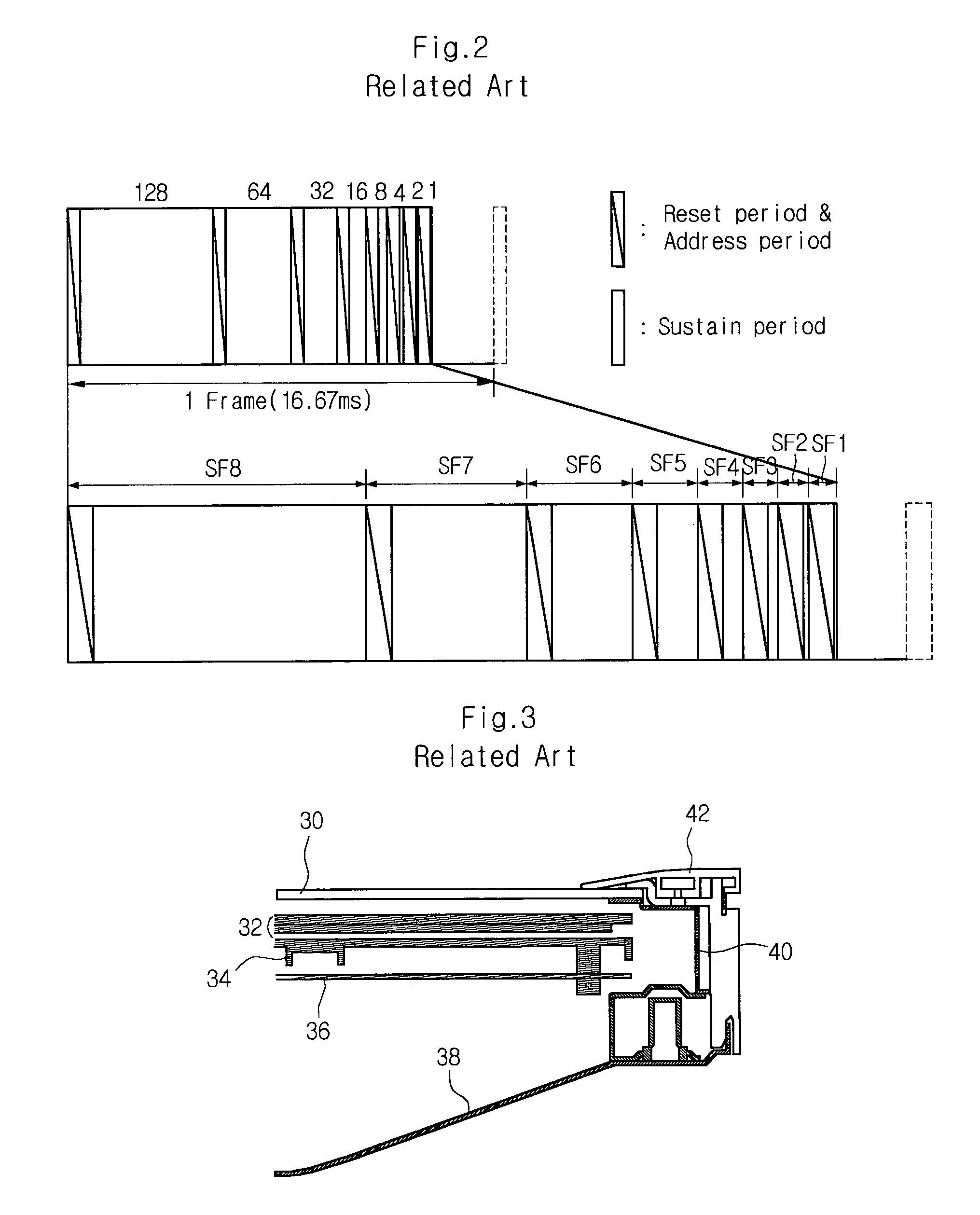
However, one of disadvantages of using the glass 54 is that the thickness of the front filter 30 with the glass 54 is increased.
In addition, when the glass 54 is inserted to the front filter 30, total weight and cost of manufacture are increased.
When the NIR is ejected to the outside, signal-transmitting devices like a remote controller for transmitting signals via IR do not work.
As a result, signals cannot be transmitted to the PDP any more.
That is to say, the ejection of the NIR causes malfunction of the remote controller.
For instance, when it is necessary to express a white color using R, G, and B colors, a yellowish white is displayed instead, or it is sometimes difficult to express flesh color.

Method used


Image

  • Front filter in plasma display panel
  • Front filter in plasma display panel
  • Front filter in plasma display panel

Examples


first embodiment

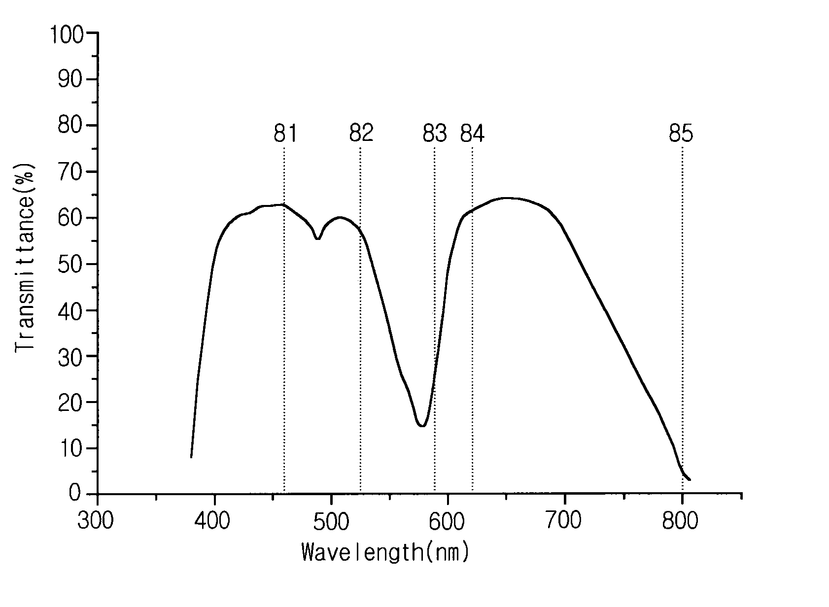
[0057]Referring to the transmittance curve shown in FIG. 8, which is achieved with the front filter according to the invention, transmittance of B rays 81 at a wavelength of 454 nm is 50–80%, transmittance of G rays 82 at a wavelength of 525 nm is 40–80%, transmittance of orange rays 83 at a wavelength of 580–592 nm is 5–30%, transmittance of R rays 84 at a wavelength of 610–630 nm is 50–80%, and transmittance of NIR 85 at a wavelength of 850–950 nm is 1–10%.

[0058]Compared to transmittance achieved with a related art front filter, the transmittance of G rays 82 has been increased considerably by 20% to 30%, resulting in a remarkable increase of color temperature, and the transmittance of orange rays 83 has been reduced by 20–30%, resulting in a remarkable increased of color purity. Besides, by designing the transmittance curve to have an increased slope at the NIR 85 wavelength range, manufacturers can greatly reduce the transmittance of NIR 85 that is known to cause malfunction of ...

second embodiment

[0062]Referring to the transmittance curve shown in FIG. 9, which is achieved with the front filter according to the invention, transmittance of B rays 91 at a wavelength of 454 nm is 60–70%, transmittance of G rays 92 at a wavelength of 525 nm is 60–70%, transmittance of orange rays 93 at a wavelength of 580–592 nm is 5–20%, transmittance of R rays 94 at a wavelength of 610–630 nm is 60–70%, and transmittance of NIR 95 at a wavelength of 850–950 nm is 1–5%.

[0063]In FIG. 9, a sharp absorption peak 96 is formed at 480–500 nm between the G rays 92 and the R rays 94, and as a result thereof, the difference between the transmittances of B rays 91 and G rays 92 and the transmittance at the wavelength range with the absorption peak 96 is 10–20%.

[0064]Also, when a sharp absorption peak 96 is formed at 580–600 nm between the G rays 92 and the R rays 94, the difference between the transmittances of B rays 91 and G rays 92 and the transmittance at the wavelength range with the absorption peak...


PUM

PropertyMeasurementUnit
Fractionaaaaaaaaaa
Fractionaaaaaaaaaa
Fractionaaaaaaaaaa

Abstract

Disclosed is a front filter attached to a front surface of a plasma display panel, the front filter comprising: an antireflection coating for preventing reflection of incident light from outside; an optical characteristic film for improving optical characteristics of incident light from the panel, by decreasing brightnesses of red (R) and green (G) rays and by increasing brightness of blue (B) rays; an EMI shielding film for shielding emission of electromagnetic wave; and an NIR blocking film for blocking near infrared rays emitted from the panel, wherein, transmittance of emitted light from the plasma display panel when the emitted light transmits the antireflection coating, the optical characteristic film, the EMI shielding film, and the NIR blocking film is determined in dependence of wavelength of the emitted light, and wherein transmittance of B rays at a wavelength of 454 nm is 50–80%, transmittance of G rays at a wavelength of 525 nm is 40–80%, transmittance of orange rays at a wavelength of 580–592 nm is 5–30%, transmittance of R rays at a wavelength of 610–630 nm is 50–80%, and transmittance of NIR at a wavelength of 850–950 nm is 1–10%.

Description

CROSS-REFERENCE TO RELATED APPLICATIONS[0001]Pursuant to 35 U.S.C. § 119(a), this application claims the benefit of earlier filing date and right of priority to Korean Application No. 8838 / 2003, filed on Feb. 12, 2003, the contents of which are hereby incorporated by reference herein in their entirety.BACKGROUND OF THE INVENTION[0002]1. Field of the Invention[0003]The present invention relates in general to a plasma display panel, more particularly, to a front panel attached to a front surface of the plasma display panel.[0004]2. Discussion of the Background Art[0005]Principle of plasma display panel displays (hereinafter referred to as PDP) technology is that 147 nm-ultraviolet rays generated by discharge of different compositions of inert gas mixtures, such as, He+Xe, Ne+Xe or He+Ne+Xe, irradiate phosphors emitting in either red, green, or blue to display images including characters or graphics. The PDP technology is at mass production stage, and recent advances in PDP technologie...

Claims


Application Information

Patent Timeline
IPC IPC(8): H01J5/16B32B17/06G02B5/08H01J17/49H01J61/40G02B5/20G02B1/11G02B5/22G09F9/00H01J11/12H01J11/44H05K9/00
CPCH01J11/12H01J11/44H01J2211/442H01J2211/446H01J2211/448
Inventor KIM, KYUNG KUCHA, HONG RAEKIM, YOUNG SUNGCHANG, MYEONG SOORYU, BYUNG GIL
Owner LG ELECTRONICS INC
Learn More