Shimmed magnetic resonance imaging apparatus and shimming method therefor

a magnetic resonance imaging and magnetic resonant equipment technology, applied in the direction of magnetic measurements, instruments, measurement devices, etc., can solve the problems of reduced openness, significant increase in costs, complex and weight of magnetic resonant equipmen

Inactive Publication Date: 2007-05-15
SIEMENS HEALTHCARE GMBH
View PDF10 Cites 6 Cited by
  • Summary
  • Abstract
  • Description
  • Claims
  • Application Information

AI Technical Summary

Benefits of technology

[0015]An object of this invention is to provide a shimming method which can effectively cover a target of an irregular object to be examined by magnetic resonant equipment.
[0024]By using the shimming method for an irregular object to be examined by magnetic resonant equipment according to the invention to design the homogeneous region, the following advantages can be achieved:
[0026](2) The volume reduction of the homogeneous region, it leads to the reduction or decrease of the size, weight and complexity of the magnets in the magnetic resonant equipment, therefore its openness is improved and also the manufacturing costs of the magnetic resonant equipment is reduced accordingly.

Problems solved by technology

Conventionally, in order to achieve a larger homogeneous region, the size, complexity and weight of magnetic resonant equipment (scanners) have been increased dramatically, leading to a significant increase in costs.
At the same time, due to the above reason, the size increase of the magnetic resonant equipment leads to reduced openness, therefore to restriction as to the applications for such scanners.
Although during the design stage the magnets are made as homogeneous as possible, the magnetic field homogeneity produced by the manufactured magnets is usually not as good as expected, so the final magnetic field homogeneity has to be achieved by shimming, such as by adding soft magnetic or hard magnetic shims onto the magnetic poles.
Small shims, however, generate in their vicinity a spatial inhomogeneity of higher powers, which makes it very difficult to perform shimming close to a magnetic pole.
Therefore, in the above schemes, the magnet design optimization improves the magnetic field's overall homogeneity to a certain degree, but cannot solve the problem of creating redundant homogeneous regions having no contribution to image quality.
The use of an ellipsoidal shaped field region instead of a spherical shaped field region for shimming can reduce the homogeneous regions having no contribution to image quality to a certain degree, but this still is not sufficient when scanning an irregular object to be examined that has a more complicated shape.
Designing different imaging sequences to reduce requirements to field homogeneity can reduce equipment costs, but nevertheless cannot solve the problem of non-contributing homogeneous regions, and the use of different imaging sequences leads to long acquisition times and slow image formation speed.

Method used


Image

  • Shimmed magnetic resonance imaging apparatus and shimming method therefor
  • Shimmed magnetic resonance imaging apparatus and shimming method therefor
  • Shimmed magnetic resonance imaging apparatus and shimming method therefor

Examples


first embodiment

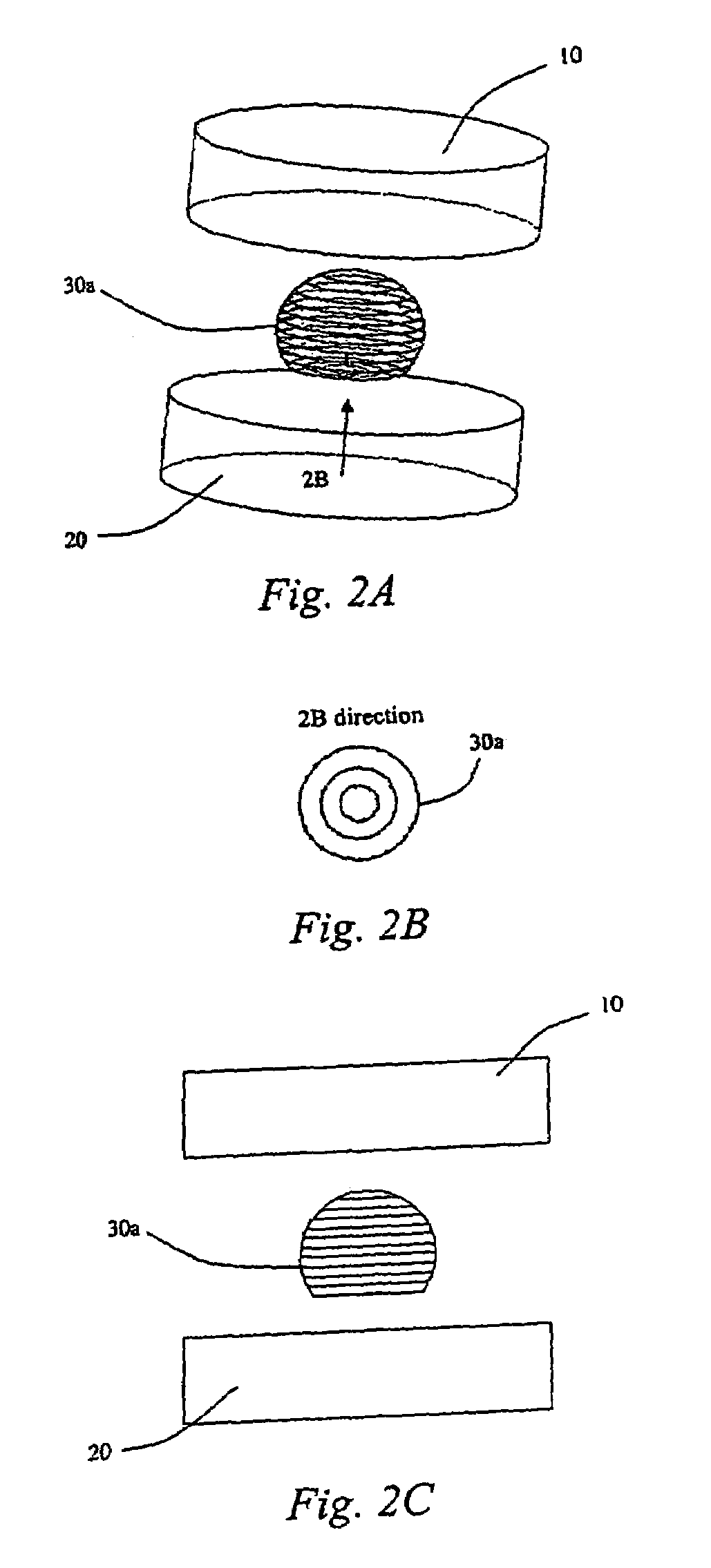
[0039]This embodiment is similar to the first embodiment, with the difference that the flat top and bottom with circular cross-section are set respectively to the upper and lower parts of the spherically shaped homogeneous regions 30b formed between the upper and lower magnetic poles 10 and 20, so as to have more effective coverage of the irregular object to be examined. This reduces the volume of the homogeneous region that has no contribution to the image quality. At the same time a number of measurement points are set on the surface of this spherical shaped homogeneous region 30b and its flat top and bottom in order to measure its magnetic parameters.

[0040]FIGS. 4A–4C show a third embodiment of the shimming method for an irregular object to be examined by magnetic resonant equipment according to the invention. FIG. 4A is a perspective view of the third embodiment of the shimming method for an irregular object to be examined by magnetic resonant equipment according to the inventio...

third embodiment

[0043]This embodiment is similar to the third embodiment with the difference that an ellipsoidal shaped homogeneous region 30d is formed between the upper and lower magnetic poles 10 and 20, and this ellipsoidal shaped homogeneous region 30d can effectively reduce in the direction of its short axis the volume of the homogeneous region which has no contribution to the image quality. The upper and lower parts of this spherical shaped homogeneous region 30d are respectively set with flat top and bottom with circular cross-section so as to have more effective coverage of said irregular object to be examined, and at the same time a number of measurement points are set on the surface of this spherical shaped homogeneous region 30d and its flat top and bottom in order to measure its magnetic parameters.

[0044]FIGS. 6A–6C show a fifth embodiment of the shimming method for an irregular object to be examined by magnetic resonant equipment according to this invention. FIG. 6A is a perspective v...

fifth embodiment

[0047]This embodiment is similar to the fifth embodiment, with the difference being that an ellipsoidal shaped homogeneous region 30f is formed between the upper end lower magnetic poles 10 and 20, and the upper and lower parts of this ellipsoidal shaped homogeneous region 30f are respectively set as a flat top with a circular cross-section and a flat bottom with an elliptic cross-section so as to have more effective coverage of said irregular object to be examined. This reduces the volume of the homogeneous region which has no contribution to the image quality; and at the same time a number of measurement points are set on the surface of this spherical shaped homogeneous region 30f and its flat top and bottom in order to measure its magnetic parameters.

[0048]Understandably, in the above embodiments of the shimming method for an irregular object to be examined by magnetic resonant equipment according to this invention, the homogeneous region can be adjusted according to circumstance...


PUM


Abstract

In a shimming method for an irregular object to be examined by magnetic resonant equipment magnetic field parameters are measured at measurement points located on the surface of an irregular object to be examined. Based on the measured magnetic field parameters, the positions and number of shims for adjusting magnetic field homogeneity are calculated when a passive shimming is to be performed, or the current value in a shimming coil are calculated when an active shimming is to be performed, or at the same time both the positions and number of shims and current value in the shimming coil are calculated when active shimming and passive shimming are to be performed at the same time. Shimming is then performed according to the calculated results. These above steps are repeated until achieving required magnetic field homogeneity. Since the homogeneous region is designed to have an irregular shape, it can provide a better coverage of the irregular object to be examined, and at the same time it reduces the shimming constraints to the unnecessary regions outside the irregular object to be examined, therefore avoiding shimming in those unnecessary regions.

Description

BACKGROUND OF THE INVENTION[0001]1. Field of the Invention[0002]The present invention relates to a shimmed magnetic resonance imaging apparatus and method for shimming magnetic resonant equipment, particularly a shimming method for an irregular object to be examined by magnetic resonant equipment.[0003]2. Description of the Prior Art[0004]In magnetic resonant equipment, the degree of magnetic field homogeneity has direct influence on the image quality. Within a scan region, the larger the homogeneous region, the better the image quality. Conventionally, in order to achieve a larger homogeneous region, the size, complexity and weight of magnetic resonant equipment (scanners) have been increased dramatically, leading to a significant increase in costs.[0005]At the same time, due to the above reason, the size increase of the magnetic resonant equipment leads to reduced openness, therefore to restriction as to the applications for such scanners.[0006]For an open and flat magnet, such as...

Claims


Application Information

Patent Timeline
Patent Type & Authority Patents(United States)
IPC IPC(8): G01V3/00
CPCG01R33/3873G01R33/3875
Inventor NI, CHENGCAO, HUICHEN, JIN JUNREN, ZHONG YOU
Owner SIEMENS HEALTHCARE GMBH
Why Eureka
Try Eureka