Device having improved heat dissipation

a technology of heat dissipation device and display panel, which is applied in the direction of static indicating device, identification means, instruments, etc., can solve the problems of ic malfunction and heat generated by the ic disposed within the space, and achieve the effect of efficient dissipation of heat generated

Inactive Publication Date: 2007-05-15
SAMSUNG SDI CO LTD
View PDF31 Cites 44 Cited by
  • Summary
  • Abstract
  • Description
  • Claims
  • Application Information

AI Technical Summary

Benefits of technology

[0011]The present invention provides a device having a heat radiator to efficiently dissipate heat generated by an IC connected to a flexible printed cable to the outside from a space in which the IC is disposed.

Problems solved by technology

However, the heat generated by the IC disposed within a space is not freely dissipated since the space in which the flexible printed cable is disposed is surrounded by the chassis base and the cover plate.
When the heat dissipation efficiency is lowered, heat can be accumulated in a greater amount in the IC than at an appropriate level, which may lead to a malfunction of the IC.

Method used


Image

  • Device having improved heat dissipation
  • Device having improved heat dissipation
  • Device having improved heat dissipation

Examples


first embodiment

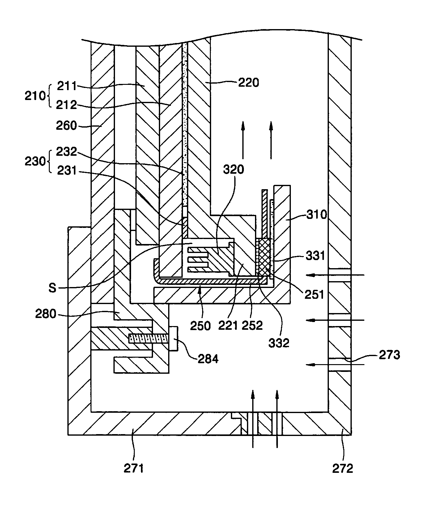
[0043]FIG. 3 is a cross-sectional view of a portion of a PDP assembly in which a heat radiator is mounted according to the present invention. Like reference numerals in the previous drawing denote like elements.

[0044]Referring to FIG. 3, the filter assembly 260, the panel assembly 210, and the chassis base 220 are arranged sequentially in the case 270. That is, the front cabinet 271 is disposed in front of the filter assembly 260, the back cover 272 is disposed at the rear of the chassis base 220, and the filter assembly 260, the panel assembly 210, and the chassis base 220 are disposed in a space formed by joining the front cabinet 271 to the back cover 272.

[0045]The chassis base 220 is attached to a back side of the rear panel 212 by the double-sided tape 231 and the heat radiation sheet 232. The chassis base 220 not only supports the panel assembly 210, but also dissipates heat generated by the panel assembly 210 during operation and transmitted through the radiation sheet 232. U...

second embodiment

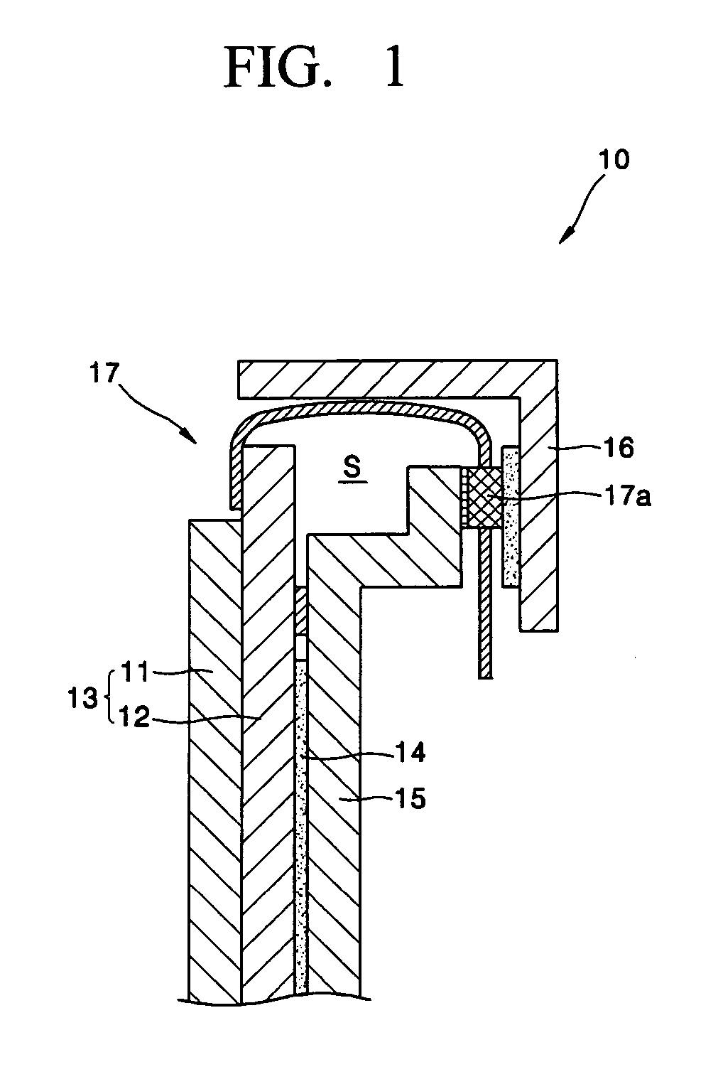
[0056]FIG. 4 is a cross-sectional view illustrating a section of a PDP assembly in which a heat radiator is mounted according to the present invention.

[0057]Referring to FIG. 4, a heat radiator, such as a heat radiation pad 420, is disposed in a space S formed by joining the panel assembly 210, the chassis base 220, and the cover plate 310.

[0058]That is, the heat radiation pad 420 is attached to an inner surface of the end part 221 of the chassis base 220 on which the IC 251 is mounted. The heat radiation pad 420 is preferably formed of a material such as a silicon rubber that can rapidly absorb the heat generated by the IC 251.

[0059]The heat generated by the IC 251 is dissipated through the chassis base 220 and can also be dissipated through the heat radiation pad 420 since the heat radiation pad 420 is mounted on an opposite side of one end 221 of the chassis base 220 on which the IC 251 is mounted.

[0060]As described above, the device according to the present invention can rapidly...


PUM


Abstract

A device having an improved heat dissipation includes: a panel assembly, a chassis base to support the panel assembly, a circuit substrate coupled to the chassis base, a flexible printed cable, respective ends of which are connected to electrode terminals of the panel assembly and a connector of the circuit substrate, the flexible printed cable transmitting electrical signals therebetween, and a heat radiator to dissipate heat generated by an IC and mounted on the chassis base on which the IC of the flexible printed cable is attached. The device can rapidly dissipate heat generated by an IC during operation since a heat radiator is disposed on one end of the chassis base corresponding to the IC of the flexible printed cable. Accordingly, an operating temperature of the IC can be maintained at an appropriate level, thereby improving the reliability of the IC.

Description

CLAIM OF PRIORITY[0001]This application makes reference to, incorporates the same herein, and claims all benefits accruing under 35 U.S.C. §119 from an application for PLASMA DISPLAY PANEL ASSEMBLY HAVING THE IMPROVED PROTECTION AGAINST HEAT earlier filed in the Korean Intellectual Property Office on 28 Nov. 2003 and there duly assigned Serial No. 2003-85773.BACKGROUND OF THE INVENTION[0002]1. Field of the Invention[0003]The present invention relates to a device, such as a Plasma Display Panel (PDP) assembly, and more particularly, to a device having improved heat dissipation of heat generated by an Integrated Circuit (IC) chip.[0004]2. Description of the Related Art[0005]A PDP assembly is a flat display device displaying images using light emitted from a gas filled discharge space in response to ultraviolet rays generated by applying a predetermined voltage to electrodes arranged on substrates facing each other.[0006]The PDP assembly is fabricated by assembling separately formed fr...

Claims


Application Information

Patent Timeline
Patent Type & Authority Patents(United States)
IPC IPC(8): H05K7/20G09G3/28H01J17/28G09F9/00G12B15/06H05K7/00
CPCH05K7/20H01J2217/49Y10S345/905H01J17/28
Inventor KIM, KI-JUNG
Owner SAMSUNG SDI CO LTD
Why Eureka
Try Eureka