
Monitor and method for controlling power-on and power-off of host computer

a monitor and host computer technology, applied in the field of monitors, can solve the problems of unusable, high fabrication cost, and inability to be used, and achieve the effect of reducing the manufacturing cost and increasing the efficiency of signal transmission

Active Publication Date: 2007-05-15
ACER INC
View PDF9 Cites 24 Cited by
  • Summary
  • Abstract
  • Description
  • Claims
  • Application Information

AI Technical Summary

Benefits of technology

"The present invention provides a monitor and method for controlling power-on and power-off of a host computer to reduce fabricating cost and increase efficiency of signal transmission. The monitor includes a switch device, monitoring device, and transmission device. The switch device changes its status in response to external force. The monitoring device monitors the change of the switch device and determines if a power management event is activated. The transmission device transmits a power management signal to the host computer to perform a power-on or power-off operation based on the activation of the power management event. This invention simplifies the process of controlling power-on and power-off of a host computer."

Problems solved by technology

A computer system in the S2 mode not only shuts down the monitor and hard drives, but also interrupts power to be supplied to the CPU and its cache.
As such, when the host computer is to be started, the user needs to bend down to press the power button, which is not user-friendly.
The fabrication cost of this LCD monitor having an internal USB hub is relatively high.
However, such means of waking up the host computer by signal transmissions from the USB device to the LCD monitor and then from the LCD monitor to the host computer is inefficient.
Furthermore, two power supply apparatuses are required by the LCD monitor to generate driving power for the USB controller and the USB hub, which is not cost effective.

Method used


Image

  • Monitor and method for controlling power-on and power-off of host computer
  • Monitor and method for controlling power-on and power-off of host computer
  • Monitor and method for controlling power-on and power-off of host computer

Examples


Embodiment Construction

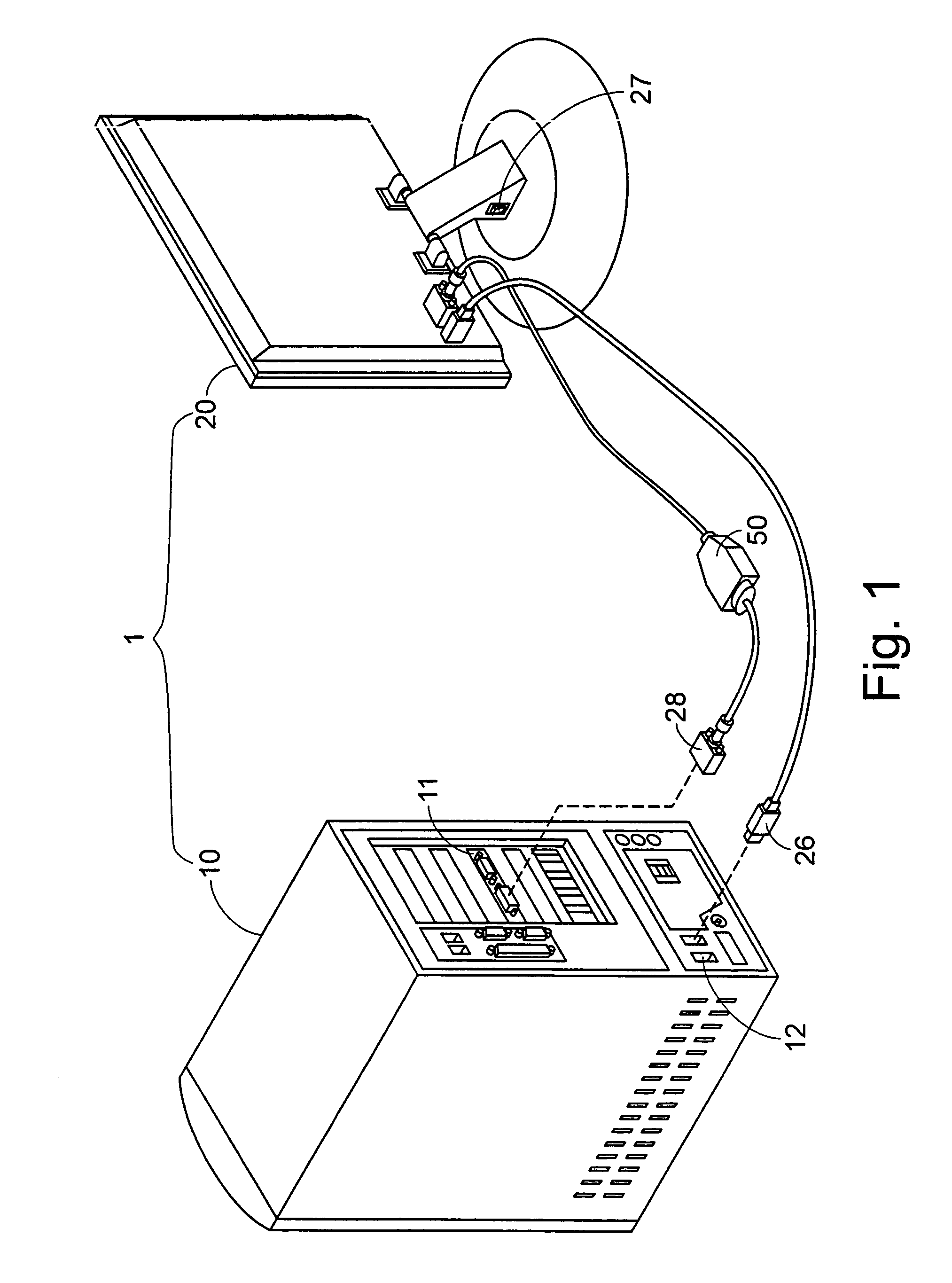
[0016]Referring to FIG. 1, a computer system according to an embodiment of the present invention is shown. The computer system 1 comprises a host computer 10 and a LCD monitor 20. The host computer 10 comprises a plurality of hardware components such as a graphic card 11. The LCD monitor 20 comprises a switch device 27 such as a multistage electronic / mechanic switch. A digital video interactive (DVI) cable 50 and a USB cable are employed to connect the LCD monitor 20 and the host computer 10, respectively. The DVI cable 50 comprises a video connector 28 connected to the graphic card 11 of the host computer 1, and the USB cable comprises a USB connector 26 connected to a USB port 12 of the host computer 1.

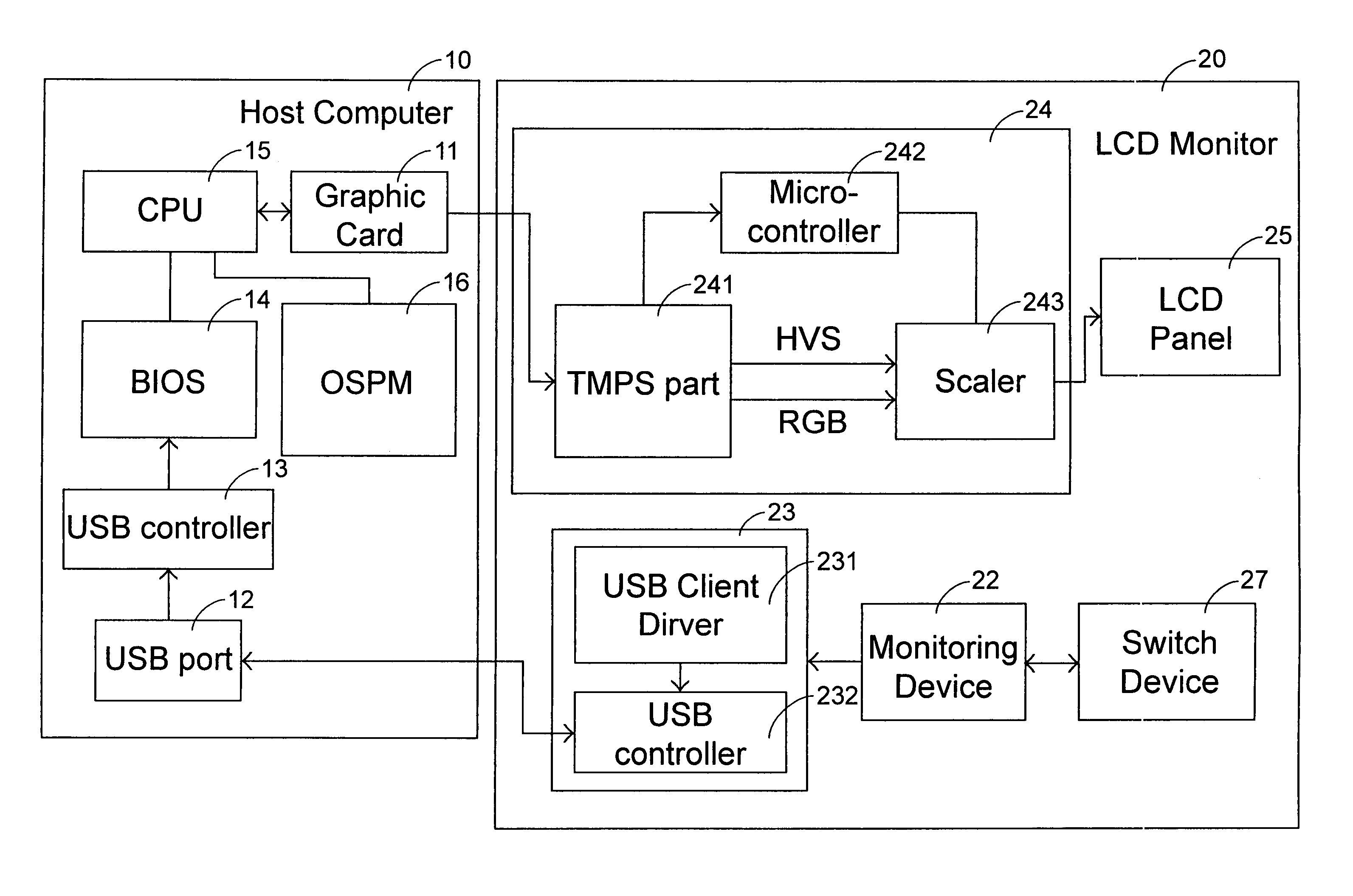
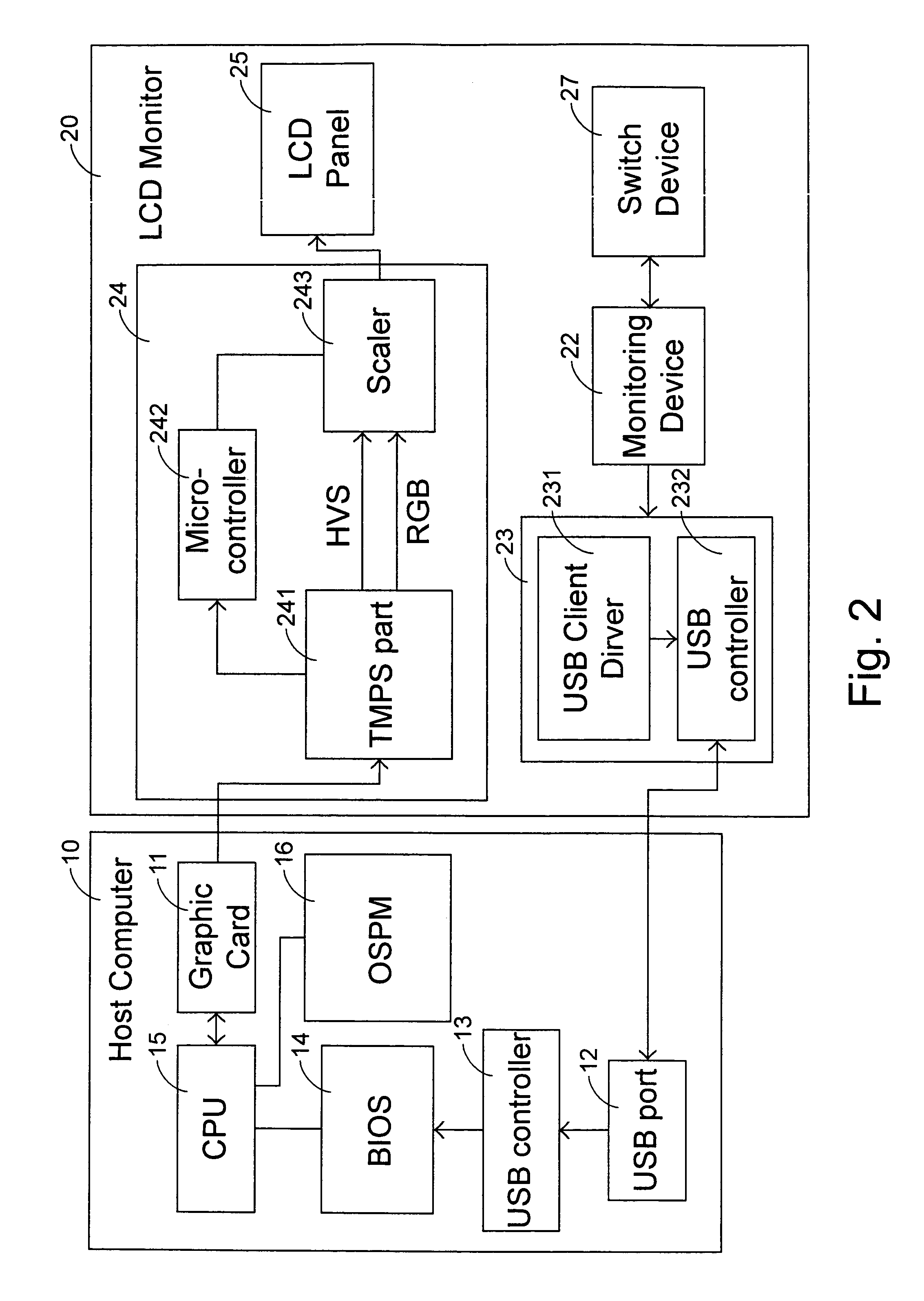
[0017]Referring to FIG. 2, a block diagram illustrating the connection of the LCD monitor and the host computer is shown. The LCD monitor 20 comprises a switch device 27, a monitoring device 22, a transmission device 23, a control chip module 24 and a LCD panel 25. The host computer...


PUM


Abstract

A monitor for controlling power-on and power-off of a host computer includes a switch device, a monitoring device and a transmission device. The host computer has a processing device. The switch device is used for changing a status thereof in response to an external force applied thereto. The monitoring device is electrically connected to the switch device for monitoring the change of the status of the switch device, and determines if a power management event is activated by the change of the status of the switch status. The transmission device is electrically connected to the monitoring device, and transmits a power management signal to the host computer according to the determination that the change of the status of the switching device activates a power management event, such that the processing device performs a startup power-on or a power-off operation on the host computer.

Description

FIELD OF THE INVENTION[0001]The present invention relates to a monitor, and more particularly to a monitor for controlling power-on and power-off of a host computer. The present invention also relates to a control method of powering on and powering off the host computer by such monitor.BACKGROUND OF THE INVENTION[0002]A power management system is widely used to save power consumption in a personal computer system. Advanced Configuration and Power Management Interface (ACPI), which was published by Intel, Microsoft and Toshiba in Dec. 22, 1996, is a specification defining standard interfaces for hardware configuration and power management of a power-saving system. According to the ACPI specification, the function of power management is integrated into the operation system to increase the efficiency of power management and the processing speed of the computer system.[0003]According to the ACPI specification, the power management of the computer system is classified into six modes incl...

Claims


Application Information

Patent Timeline
Patent Type & Authority Patents(United States)
IPC IPC(8): G06F1/26G06F1/32
CPCG06F1/3215G06F1/3218
Inventor O, CHIH-PING
Owner ACER INC
Learn More