Backing ring for railcar axle

a technology for railcar axles and backing rings, which is applied in the direction of mechanical equipment, rigid support of bearings, transportation and packaging, etc., can solve the problems of flexing cyclically, affecting the stability of bearings,

Active Publication Date: 2007-05-22
THE TIMKEN CO
View PDF15 Cites 36 Cited by
  • Summary
  • Abstract
  • Description
  • Claims
  • Application Information

AI Technical Summary

Problems solved by technology

Being subject to considerable weight, the journals flex cyclically as wheels roll along the rails of a railroad track, with most of the flexure occurring near the small ends of the fillets.
The flexure produces fretting between the backing ring and the fillets, and as a consequence both experience wear.
When water seeps into the spaces between the backing rings and the fillets, it exacerbates the fretting with corrosion.
Sometimes the wear at a journal is enough to eliminate the clamp fit that holds the bearing in place, and this disturbs the setting for the bearing, imparting more end play than desired.
This contributed to axle flexing of a higher magnitude which in turn led to greater fretting wear.

Method used


Image

  • Backing ring for railcar axle
  • Backing ring for railcar axle
  • Backing ring for railcar axle

Examples


Embodiment Construction

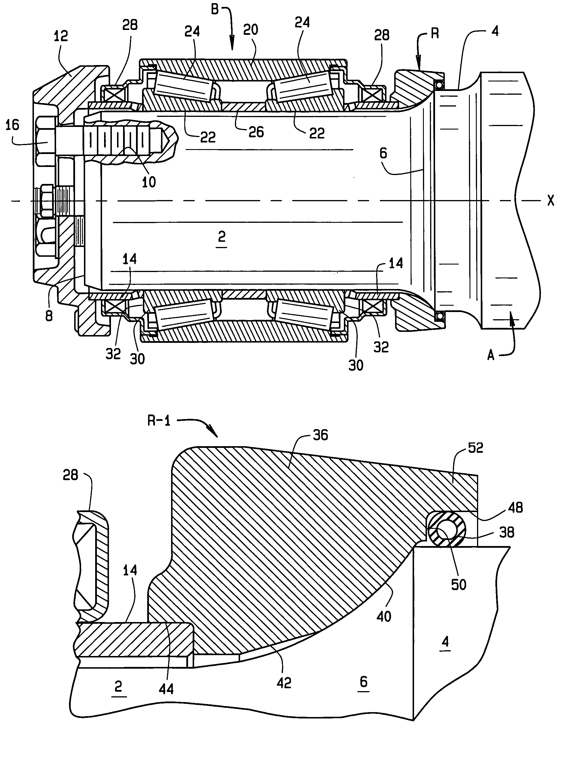
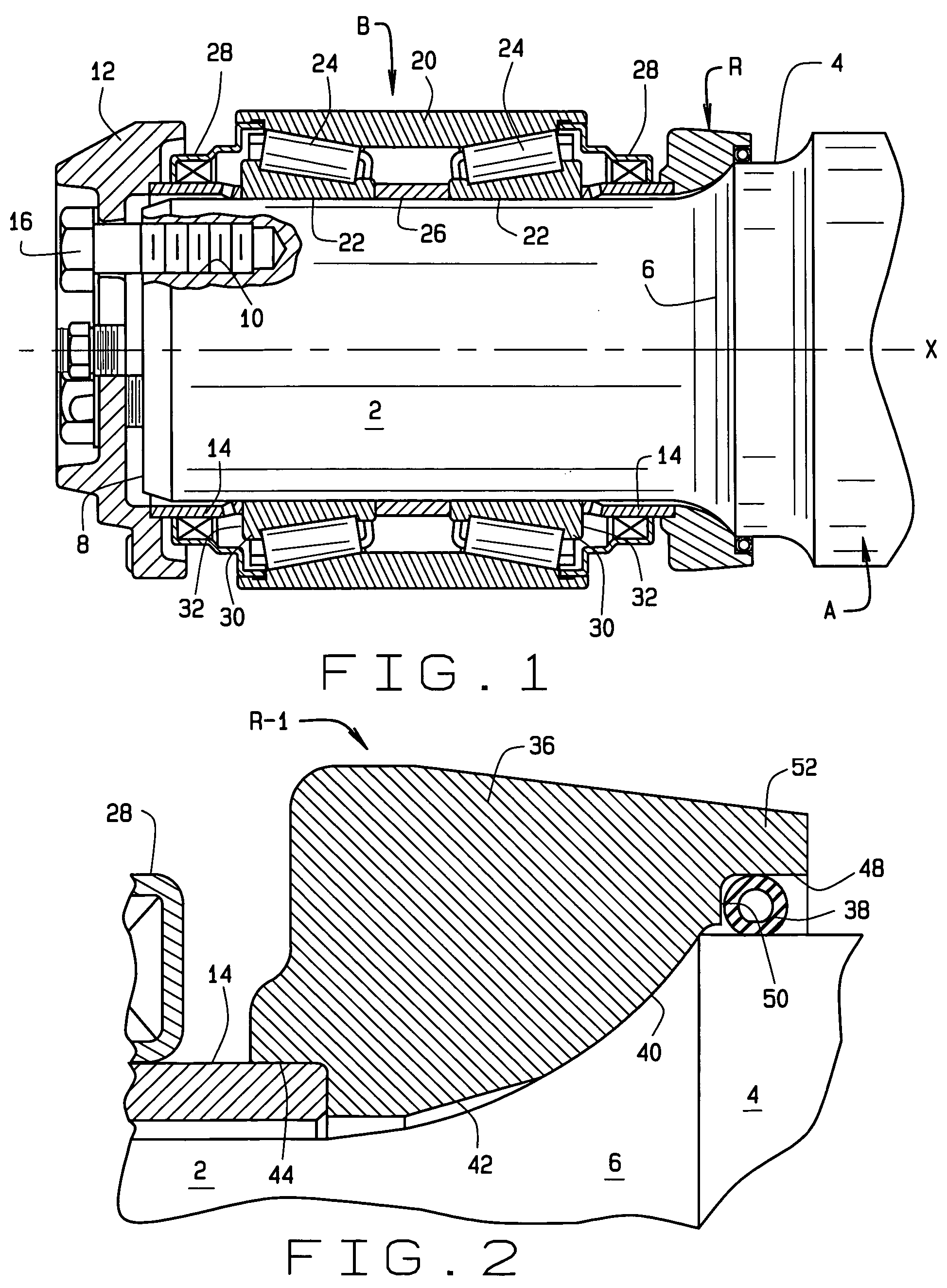
[0017]Referring now to the drawings (FIG. 1), a railcar axle A, to which wheels are fitted, rotates about an axis X as the wheels roll along the rails of a railroad track. The axle A, along with several other like axles, supports a rail car, with the weight of the rail car being transferred to the axle through bearings B.

[0018]The axle A at each of its ends has a journal 2 which leads to a somewhat larger dust guard diameter 4 at a fillet 6. Inwardly from the dust guard diameter 4 the axle A has an even larger wheel seat to which a wheel is fitted. The journal 2 extends out to an end face 8 out of which threaded holes 10 open. Both the journal 2 and the dust guard diameter 4 are cylindrical and concentric, with their common center being the axis X.

[0019]The bearing B fits around the journal 2 where it is captured between a backing ring R that bears against the fillet 6 and an end cap 12 that extends over the end face 8, yet is spaced slightly outwardly from it. The bearing B is sepa...


PUM


Abstract

A backing ring that serves to back an antifriction bearing on the journal of a rail car axle includes an annular body that seats against a fillet that is located at the end of the journal and also a lip that projects over a larger dust guard diameter that is located on the axle immediately beyond the fillet. In addition, the backing ring includes a stabilizing element which cooperates with the lip and with the dust guard diameter to lessen the tendency of the annular body to work against the fillet and create a fretting wear when the journal undergoes cyclic flexures. The stabilizing element accommodates dust guard diameters of varying size. The stabilizing element may also establish a seal between the lip and the dust guard diameter.

Description

CROSS REFERENCE TO RELATED APPLICATIONS[0001]This application derives priority from U.S. provisional application 60 / 501,353, of Stephen E. Brister et al., filed Sep. 9, 2003, and entitled “Universal Fit Backing Ring”, and from U.S. provisional application 60 / 555,482 of the same inventors, filed Mar. 23, 2004, and also entitled “Universal Fit Backing Ring”, priority being claimed from both provisional applications.STATEMENT REGARDING FEDERALLY SPONSORED RESEARCH OR DEVELOPMENTBACKGROUND OF THE INVENTION[0002]This invention relates in general to backing rings for the bearings on railroad axles and, more particularly, to stabilized backing rings that fit axles of varying diameter.[0003]The typical bearing for a railcar fits around a journal at the end of a railcar axle where it is captured between a backing ring and an end cap. The backing ring seats against a fillet that merges into an enlarged dust guard diameter, while the end cap fits over the end of the journal to which it is secu...

Claims


Application Information

Patent Timeline
Patent Type & Authority Patents(United States)
IPC IPC(8): F16C19/50B61F15/22F16C35/063
CPCB61F15/22F16C35/063F16C33/768F16C19/386F16C2326/10
Inventor BRISTER, STEPHEN E.TOTH, DAVID G.KARICH, RUDOLPH C.ANDERSON, RYAN J.FOX, GERALD P.WILLIAMS, SAMUEL R.
Owner THE TIMKEN CO
Why Eureka
Try Eureka