Pressure fluctuation prevention tank structure, electrolyte circulation type secondary battery, and redox flow type secondary battery

a technology of pressure fluctuation and tank structure, which is applied in the direction of indirect fuel cells, non-aqueous electrolyte cells, cell components, etc., can solve the problems of increasing boosting up the cost of the entire battery system, and the inability to implement a tank structure so rigid that it can withstand. , to achieve the effect of preventing a pressure variation

Inactive Publication Date: 2007-05-22
SUMITOMO ELECTRIC IND LTD +1
View PDF14 Cites 50 Cited by
  • Summary
  • Abstract
  • Description
  • Claims
  • Application Information

AI Technical Summary

Benefits of technology

[0005]Therefore, it is an object of the present invention is to provide a simplified, pressure-variation preventing tank structure capable of preventing a pressure variation resulting from a temperature variation in a gas phase portion without bringing stored liquid into contact with air, an electrolyte-circulating type secondary battery, and a redox flow secondary battery.

Problems solved by technology

As a result, the inert gas for preventing the negative pressure must be reserved, resulting in an undesired cost increase.
If an electrolyte tank for a redox flow secondary battery, for example, is to withstand this pressure variation of about 0.1 atmosphere, the structure thereof needs to be considerably rigid, which boosts up the cost of the entire battery system.
In case of the electrolyte tank for the redox flow secondary battery, it is impossible to implement a tank having so rigid a structure that can withstand the pressure variation as mentioned above, due to the constraint of locational conditions or power generation costs.

Method used


Image

  • Pressure fluctuation prevention tank structure, electrolyte circulation type secondary battery, and redox flow type secondary battery
  • Pressure fluctuation prevention tank structure, electrolyte circulation type secondary battery, and redox flow type secondary battery
  • Pressure fluctuation prevention tank structure, electrolyte circulation type secondary battery, and redox flow type secondary battery

Examples


first embodiment

[0032](First Embodiment)

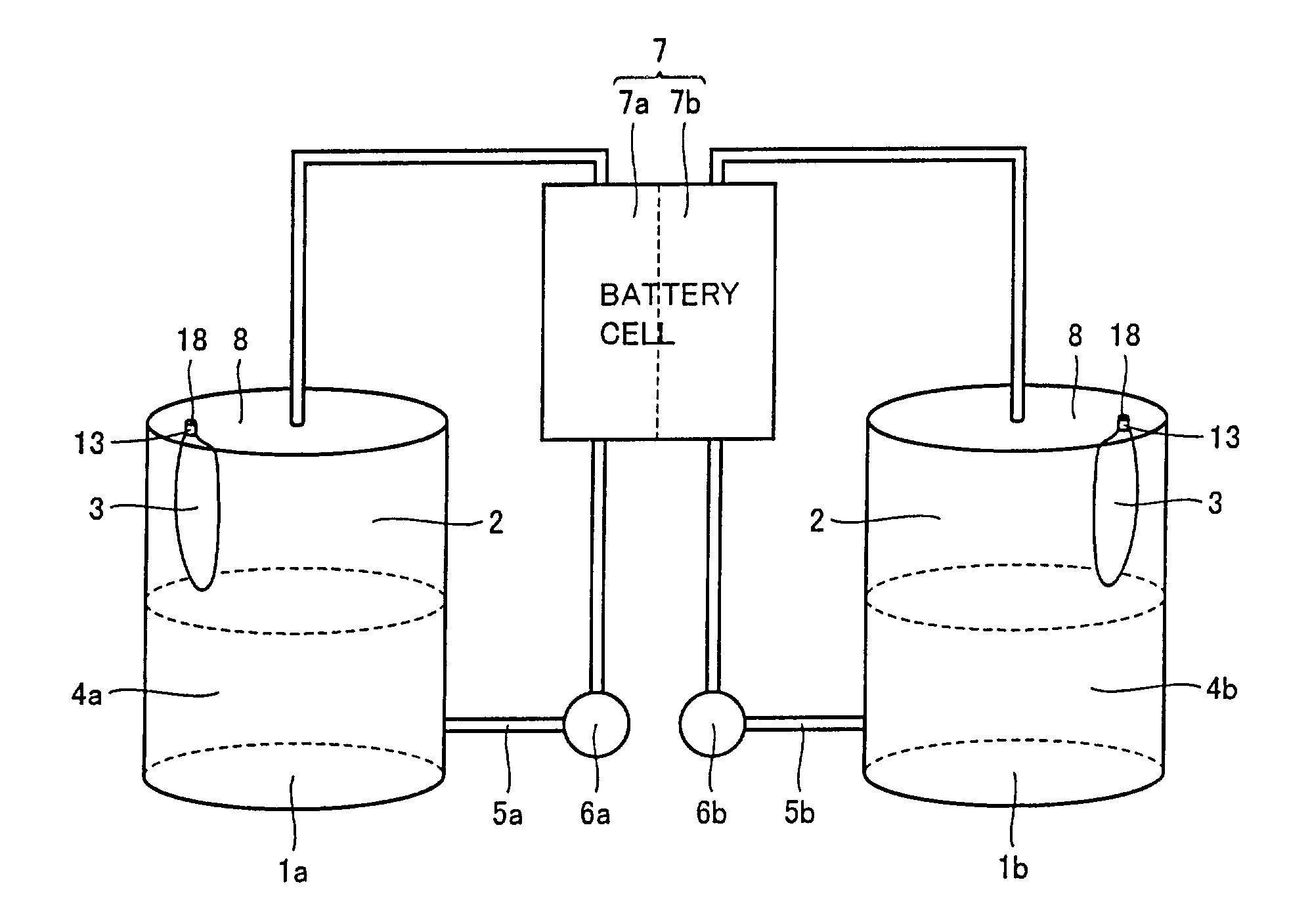
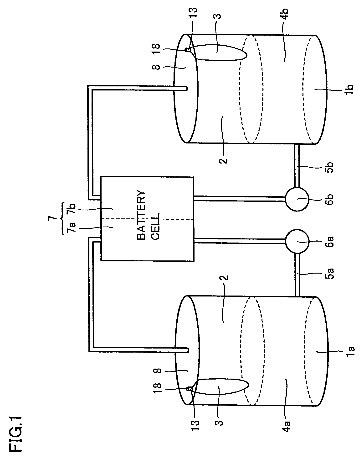
[0033]First, a first embodiment in which a pressure-variation preventing tank structure of the present invention is applied to a redox flow secondary battery will be described. Referring to FIG. 1, in a battery cell 7 of a redox flow secondary battery, positive electrolyte 4a is circulated in a positive electrode cell 7a and negative electrolyte 4b is circulated in a negative electrode cell 7b. A positive electrolyte pump 6a and a negative electrolyte pump 6b are respectively used to circulate positive electrolyte 4a and negative electrolyte 4b. The pressure-variation preventing tank structure of the present invention is used for both of the electrolyte tanks no matter whether it is positive or negative, and therefore in the following the same description will be made for both of the positive and negative electrolytes. The electrolyte tank is a polyethylene tank in both the positive and negative electrolyte tanks. It is noted that the positive electrolyte is ...

second embodiment

[0041](Second Embodiment)

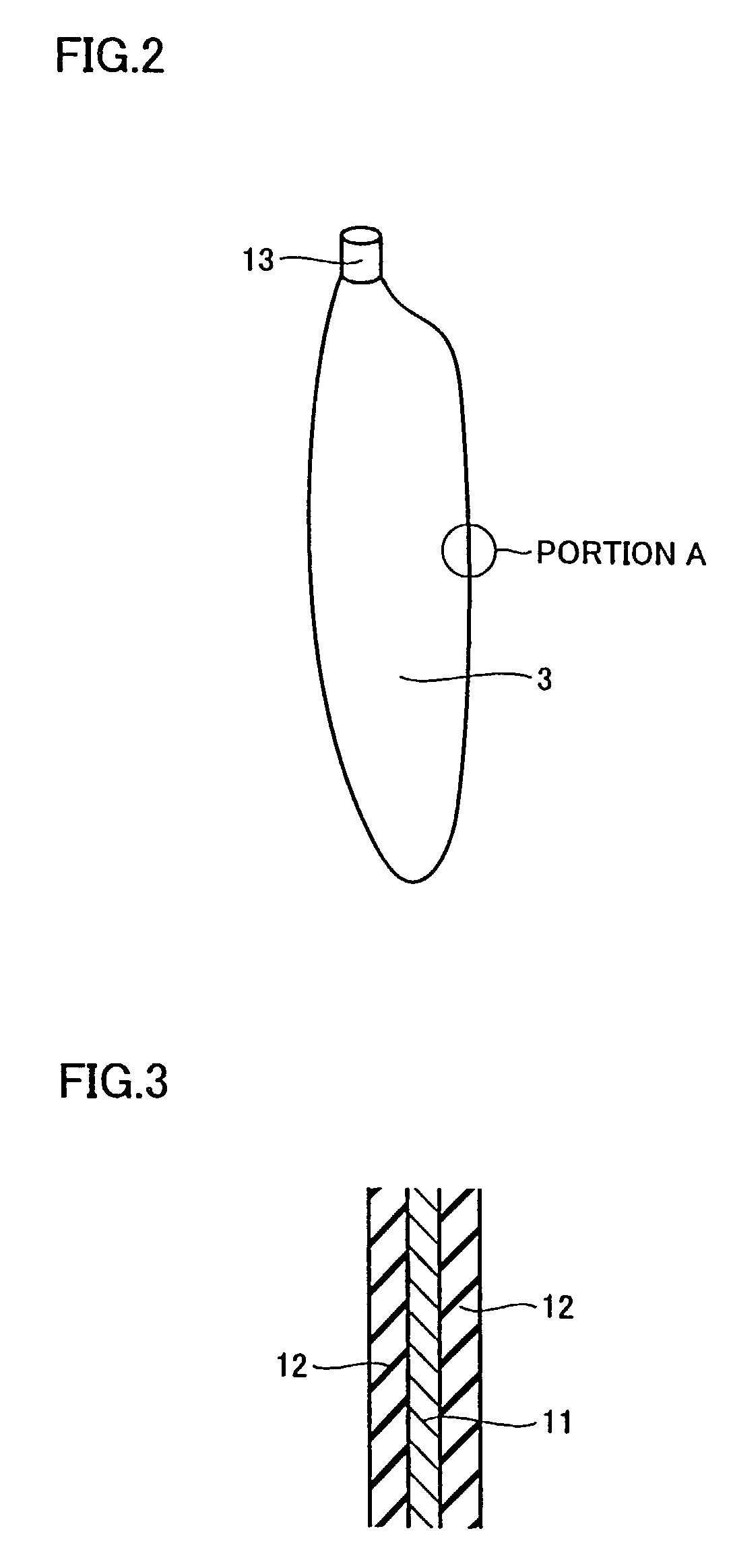
[0042]FIG. 7 shows the pressure-variation preventing tank structure in accordance with a second embodiment of the present invention. Two breather bags 3 are attached to one polyethylene tank 1. The above noted manhole 21 is provided with a vent 22 having a valve 23, and flange portion 13 of the breather bag is attached to manhole 21 by welding to communicate with outside air through vent 22.

[0043]As illustrated in the first embodiment, if the volume of the gas phase portion is 15 m3 and temperature change ΔT=32° C., approximately, volume change ΔV of about 10%, that is, about 1.5 m3 is necessary. When a breather bag having a volume of about 1 m3 is formed of the three-layered composite material shown in FIG. 3, the weight thereof is not more than 5 kgf. This weight affords its attachment to manhole 21. As shown in FIG. 7, provision of two breather bags can assure a volume change of about 10% of the volume of the gas phase portion. Depending on the magnitude ...


PUM

PropertyMeasurementUnit
temperatureaaaaaaaaaa
pressureaaaaaaaaaa

Abstract

A simplified, pressure-variation preventing tank structure capable of preventing pressure variations in a gas phase portion resulting from temperature variations, without bringing stored liquid into contact with air. This pressure-variation preventing structure includes a breather bag arranged in a gas phase portion of a tank and inflating / deflating in communication with outside air, and a manhole to which the breather bag is attached to suspend in a gas phase portion, including a communication hole for the breather bag to communicate with outside air. The breather bag has air-blocking, acid-resistant and expandable characteristics.

Description

TECHNICAL FIELD[0001]The present invention relates to a pressure-variation preventing tank structure capable of maintaining a constant internal pressure in a tank storing acid liquid, and an electrolyte-circulating type secondary battery and a redox flow secondary battery with the pressure-variation preventing tank structure.BACKGROUND ART[0002]When liquid is stored in a tank, the pressure in a gas-phase portion of the tank is variable, depending on the temperature of the stored liquid, on the reaction in a reaction portion of a battery cell, and the like. When the pressure difference between the inside and the outside of the tank is strictly limited, as in the case of a polyethylene tank etc., it is possible to make the tank a sealed structure by providing an air release valve or the like, for positive pressure. Furthermore, if the internal pressure in the tank may become negative because of a temperature drop of the stored liquid, the negative pressure is generally avoided by comm...

Claims


Application Information

Patent Timeline
Patent Type & Authority Patents(United States)
IPC IPC(8): H01M2/40B65D81/00H01M8/20H01M8/04H01M8/18H01M50/673H01M50/77
CPCH01M2/1288H01M8/04276H01M8/188H01M8/20B65D90/32H01M2/36H01M2/40Y02E60/528H01M8/04186Y02E60/50Y02E60/10H01M50/342H01M50/77H01M50/673
Inventor ITO, TAKEFUMITOKUDA, NOBUYUKI
Owner SUMITOMO ELECTRIC IND LTD
Why Eureka
Try Eureka