Stitched shielded pole structure for a perpendicular magnetic recording write head

a write head and perpendicular magnetic technology, applied in the field of magnetic recording head design, can solve the problems of super-paramagnetic limit of magnetic media becoming a problem, write head illustrated creating problems of unwanted side writing, etc., and achieve the effect of reducing unwanted side writing and adjacen

Inactive Publication Date: 2007-05-22
HEADWAY TECH INC
View PDF8 Cites 17 Cited by
  • Summary
  • Abstract
  • Description
  • Claims
  • Application Information

AI Technical Summary

Benefits of technology

[0011]A first object of this invention is to provide a write shield formation for a perpendicular magnetic recording (PMR) head that significantly reduces unwanted side writing and adjacent track erasure (ATE) as compared to conventional designs.
[0012]A second object of the present invention is to provide a write shield formation for a PMR head that produces reduced lateral flux leakage.
[0013]A third object of the present invention is to provide a write shield formation for a PMR head that produces an improved perpendicular writing field component and improved perpendicular writing field gradient.
[0015]The efficacy of the invention depends on design parameters, d and TSWS where d is one-half the difference between the width of the lower edge of the stitched write shield and the width of upper edge of the pole and TSWS is the distance between the upper and lower edges of the stitched write head. By a proper choice of the design parameters, the stitched write shield significantly reduces adjacent track erasures (ATE) and helps produce a perpendicular magnetic field with a sharp gradient.

Problems solved by technology

At this ultra-high area density, the super-paramagnetic limit of magnetic media becomes a problem, which is the condition wherein magnetic domains are so small that they lack thermal stability and can be randomly aligned by thermal agitation.
Batra et al. note that the write head illustrated will create problems of unwanted side writing because of the lack of a shielding mechanism to contain the field laterally and prevent the field from spreading beyond the track being written upon.

Method used


Image

  • Stitched shielded pole structure for a perpendicular magnetic recording write head
  • Stitched shielded pole structure for a perpendicular magnetic recording write head
  • Stitched shielded pole structure for a perpendicular magnetic recording write head

Examples


Embodiment Construction

[0025]The preferred embodiment of the present invention is a PMR head that includes a write shield formation having a stitched portion formed on a leading edge of a main portion, the stitched portion being separated from a main magnetic pole by a narrow write gap layer.

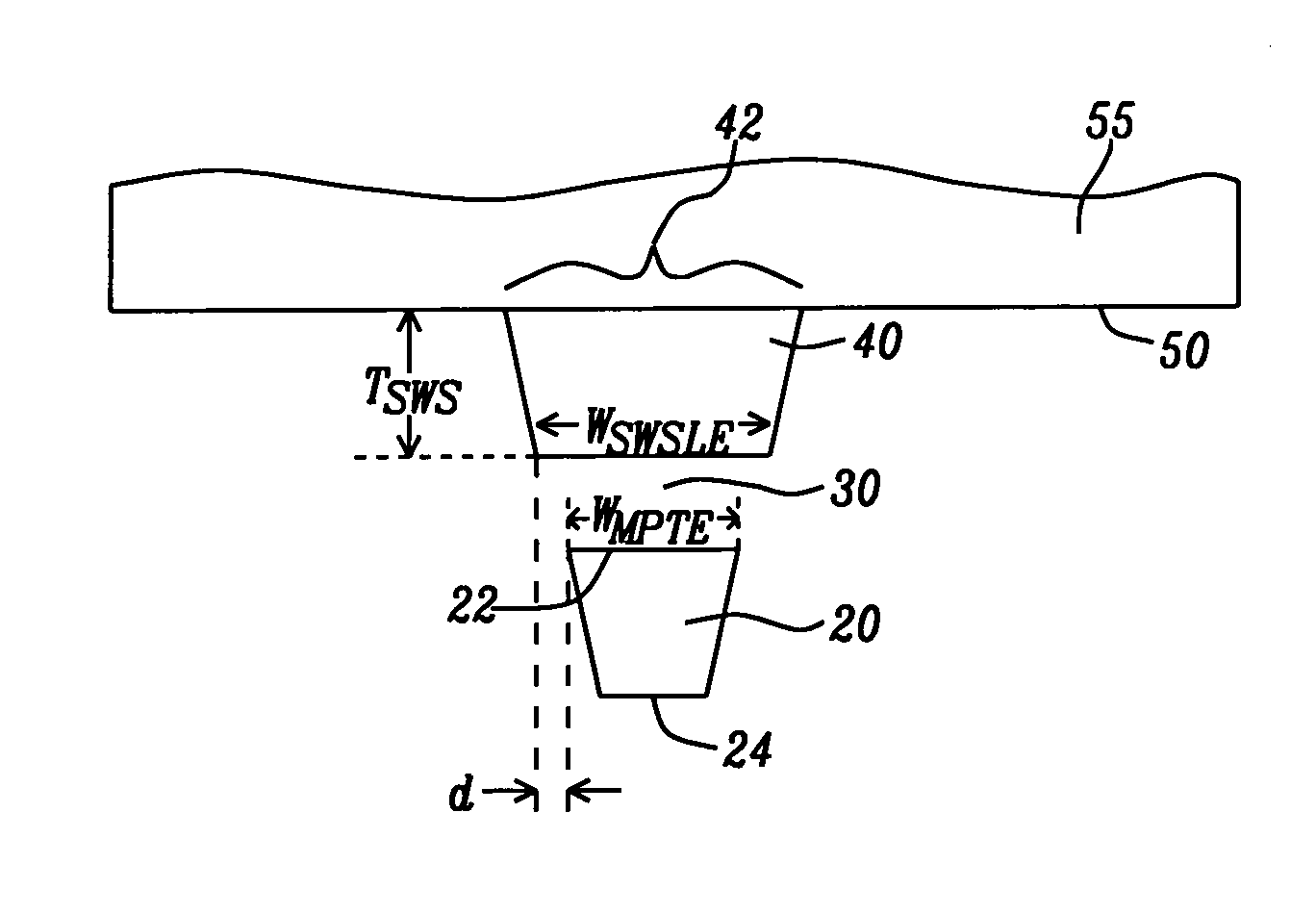
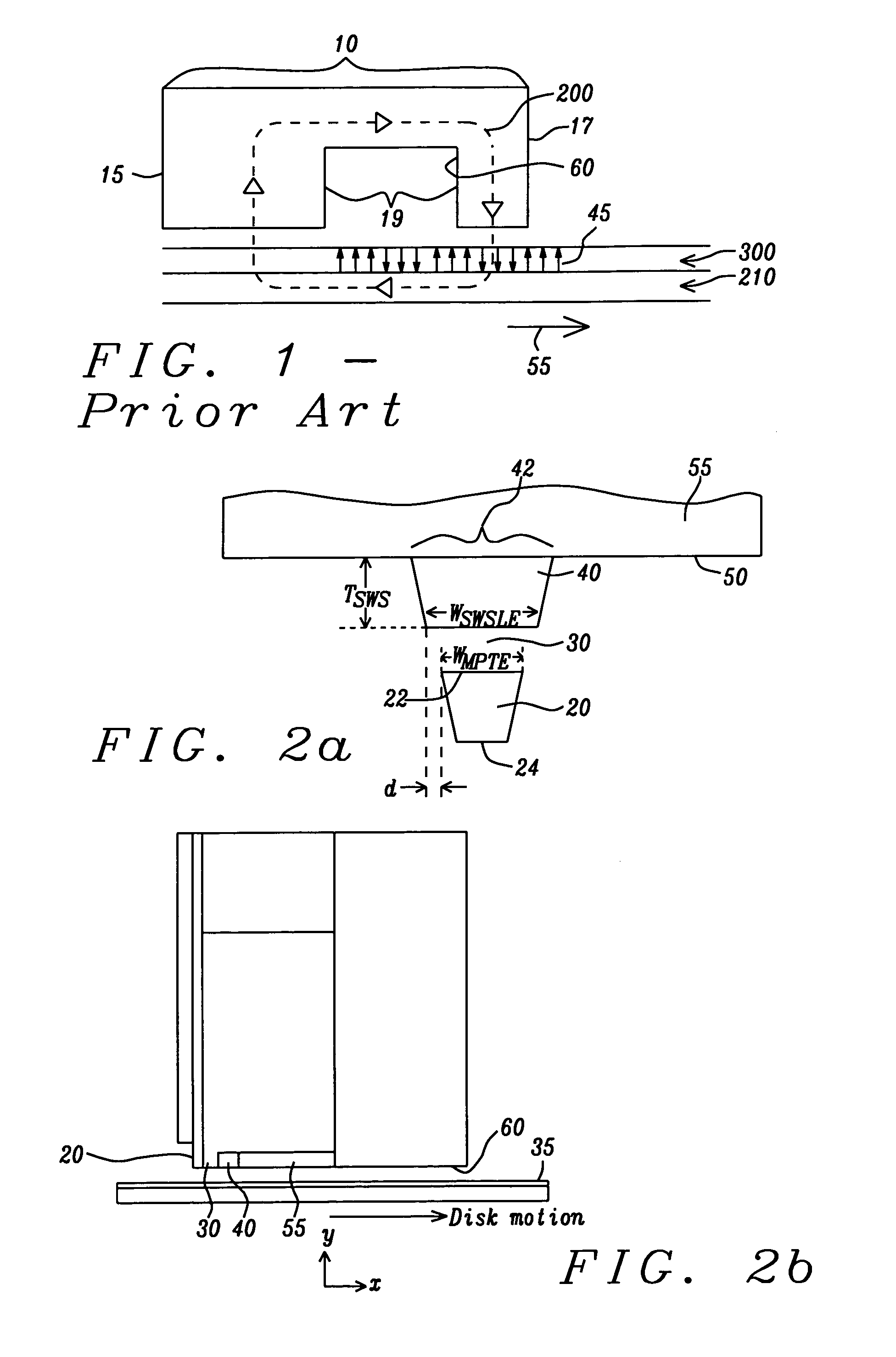
[0026]Referring to FIG. 2a, there is shown schematically a front view of the air bearing surface plane (ABS) of a preferred embodiment of the present invention. A magnetic recording medium, typically a disk, which would be in front of the figure plane, moves past this surface from bottom to top (the −x direction) as shown by the arrow. In the description that follows, edges of the pole or shields past which a given region of the medium first moves are denoted “leading” edges and edges past which that region of the medium moves last are called “trailing” edges.

[0027]The main pole (20) has, in the ABS cross-sectional plane, a truncated wedge shape of narrow dimension with a leading edge (24) and a trailing edge (22). Th...


PUM

PropertyMeasurementUnit
thicknessaaaaaaaaaa
thicknessaaaaaaaaaa
widthaaaaaaaaaa

Abstract

A PMR write head has a stitched shield formation which results in a strong perpendicular write field with sharp vertical gradients. The shape of the stitched shield is determined by two design parameters, d=½(WSWSLE−WMPTE), and TSWS, where WSWSLE is the width of the leading edge of the stitched shield in the ABS plane, WMPTE is the width of the trailing edge of the main magnetic pole in the ABS plane and TSWS is the thickness of the stitched shield. By a proper choice of these parameters, the write field of the head is sharply limited in the cross-track direction, so that adjacent track erasures are eliminated.

Description

RELATED APPLICATION[0001]This application is related to Ser. No. 10 / 849,312, Filing date May 19, 2004, assigned to the same assignee as the present Application.BACKGROUND OF THE INVENTION[0002]1. Field of the Invention[0003]This invention relates generally to the design of magnetic recording heads for high recording density, particularly heads designed for perpendicular magnetic recording.[0004]2. Description of the Related Art[0005]The commonly used inductive magnetic write head technology utilizes the longitudinal configuration. In this configuration a magnetic field fringes across a write gap between an upper and a lower pole in the plane of the air bearing surface (ABS) of the write head. This plane will be referred to as the longitudinal plane. The ABS is positioned above and parallel to the surface of a recording medium, such as a hard disk. The surface of the hard disk is formed of a magnetic medium. As the hard disk moves beneath the ABS, a horizontal component of the fringi...

Claims


Application Information

Patent Timeline
Patent Type & Authority Patents(United States)
IPC IPC(8): G11B5/31G11B5/23G11B5/127G11B5/147
CPCG11B5/1278G11B5/3113G11B5/3116G11B5/3143
Inventor TAKANO, KENICHIHAN, CHERNG-CHYI
Owner HEADWAY TECH INC
Why Eureka
Try Eureka