Heat sink fan

a technology of heat sink fan and heat sink, which is applied in the direction of piston pumps, domestic stoves or ranges, lighting and heating apparatus, etc., can solve the problems of limited lead wire free movement, and achieve the effect of enhancing convenience, enhancing the operability of packing operation and transportation

Active Publication Date: 2007-05-22
NIDEC CORP
View PDF10 Cites 50 Cited by
  • Summary
  • Abstract
  • Description
  • Claims
  • Application Information

AI Technical Summary

Benefits of technology

[0010]It is an object of the present invention to enhance the operability of the packing operation and the transportation, and to enhance the convenience when the lead wire is mounted on the electronic equipment by holding the lead wire in the housing such that the lead wire does not interfere with other electronic components.
[0014]With this configuration, it is possible to prevent entanglement of the lead wire, and prevent the lead wire from interfering with other electronic component and from being cut. It is possible to prevent a case in which the lead wire is caught on a resin product and the product is cracked. It is also possible to prevent a case in which an operator is caught on a projected lead wire to strongly pull the lead wire, and contact between the lead wire and a circuit substrate of the motor is deteriorated. Since it becomes easy to handle the lead wire, it is possible to prevent the packing operation or transportation from being complicated. The lead wire retaining hook is mounted on the cylindrical portion, and the lead wire retaining hook can be formed integrally on the cylindrical portion. Thus, the lead wire retaining hook can be produced without increasing the producing cost almost at all.

Problems solved by technology

With this, free movement of the lead wire is limited.

Method used


Image

  • Heat sink fan
  • Heat sink fan
  • Heat sink fan

Examples


first embodiment

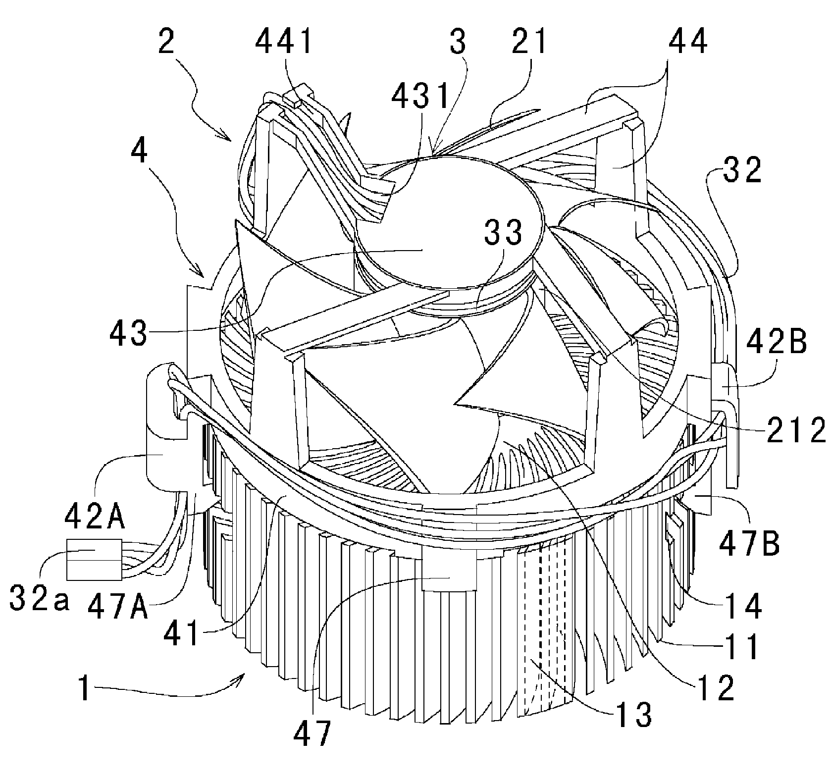
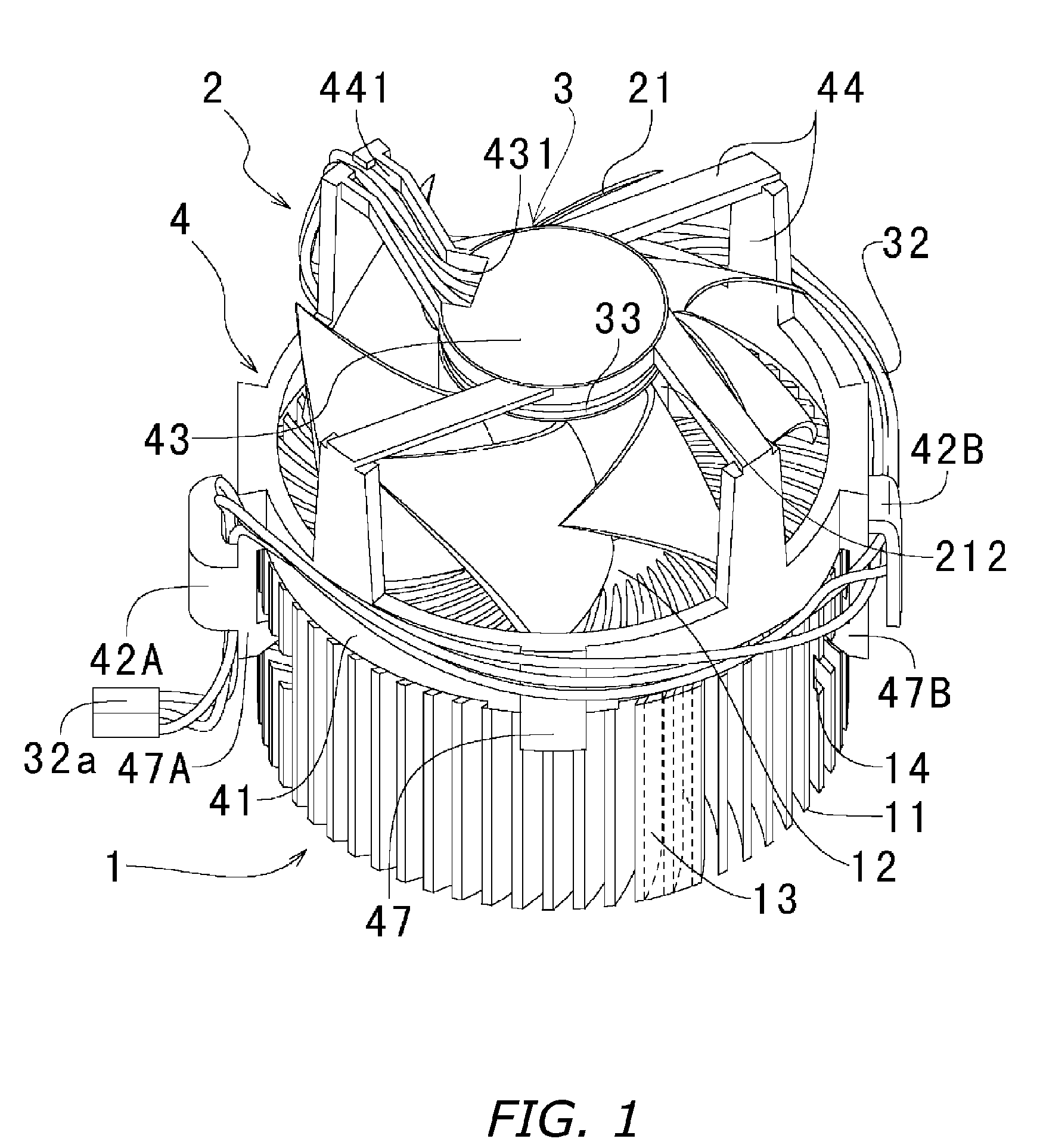
FIG. 1 is a perspective view showing a heat sink fan of a first embodiment of the invention.

[0030](1-1) Constituent Elements

[0031]A heat sink fan of the embodiment comprises a heat sink 1 and an axial flow fan 2. The heat sink 1 has plate-like metal heat radiating fins 11 radially extending from a center of the heat sink 1. The axial flow fan 2 includes an impeller 21 having a plurality of blades 211 disposed on an outer peripheral surface of a cylindrical member 212 at equal distances from one another. The axial flow fan 2 also includes a drive unit 31 of a motor 3 which rotates the impeller 21, lead wires 32 for supplying current to the drive unit 31, and a housing 4 located on an outer periphery of the impeller 21 and having a cylindrical portion 41.

[0032](1-2) Heat Sink

[0033]The radiating fin 11 radially extending from the heat sink 1 is enveloped along a cylindrical envelope surface 13, and the radiating fin 11 is shaped into a cylindrical shape as a whole. A portion of the env...

second embodiment

[0053]FIG. 8 is a perspective view of an essential portion of a heat sink fan of a second embodiment of the invention. FIG. 9 is a perspective view of the heat sink fan shown in FIG. 8 as viewed from the arm 47A. FIG. 10 is an enlarged view of its essential portion.

[0054](2-1) Constituent Elements

The heat sink fan of this embodiment has the same constituent elements as those of the heat sink fan of the first embodiment. Structures of the heat sink 1, the axial flow fan 2 and the motor 3 are also the same as those of the first embodiment.

[0055](2-2) Retaining of Lead Wire

Like the first embodiment, the lead wires 32 are pulled out toward the outer periphery of the housing 4 through the guide groove 441 provided in one of the ribs 44 which support the motor holder 43 via the lead wire-pulling out hole 431.

[0056]If the pulled out lead wire 32 is inserted into the interspace 45 from the opening 46 of the interspace 45 of the lead wire retaining hook 42, the lead wire 32 can be held. When...

third embodiment

FIG. 12 is a perspective view showing an essential portion of a heat sink fan of a third embodiment of the present invention.

[0058](3-1) Constituent Elements

The heat sink fan of this embodiment has the same constituent elements as those of the heat sink fan of the first embodiment. Structures of the heat sink 1, the axial flow fan 2 and the motor 3 are also the same as those of the first embodiment.

[0059](3-2) Retaining of Lead Wire

[0060]The cylindrical portion 41 of the housing 4 is formed with two arms 47B and 47C which are to be engaged with two heat sinks. The arms 47B and 47C are separated from each other through 180° in a circumferential direction of the cylindrical portion 41. The arm 47C is provided with two lead wire retaining hooks 42C and 42D. The lead wire retaining hooks 42C and 42D are adjacent in the circumferential direction. A interspace 45C is formed between the arm 47C and the lead wire retaining hooks 42C and 42D. An upper end of the lead wire retaining hook 42C ...


PUM


Abstract

A heat sink fan of the present invention includes a heat sink and an axial flow fan, and the axial flow fan includes a motor, an impeller and a housing. An outer wall surface of a cylindrical portion of the housing is formed with an arm which engages with the heat sink and fixes the housing and the heat sink. The arm is provided with a lead wire retaining hook. A interspace is formed between the lead wire retaining hook and the arm, and the lead wire is detachably held in the interspace. The packing or transportation operation is enhanced, and convenience of mounting operation of the lead wire to electronic equipment is enhanced.

Description

BACKGROUND OF THE INVENTION[0001]1. Field of the InventionThe present invention relates to a heat sink fan which cools an electronic component such as MPUs.[0002]2. Description of the Related Art[0003]MPUs (microprocessing unit) are incorporated in an electronic calculator and high performance electronic equipment. In recent years, as the MPU is increased in speed and reduced in size, heat generated from the MPU itself becomes serious problem. Therefore, a heat sink fan comprising a combination of a heat sink having a plurality of heat radiating fins and an axial flow fan for supplying air to the heat sink is incorporated in the electronic equipment such as the MPU which generates heat.[0004]The heat sink is positively cooled by cooling air supplied by the axial flow fan.[0005]The MPU is contained on a circuit substrate of the electronic equipment, and a power supply terminal which functions as a power supply of the heat sink fan is also provided on the circuit substrate of the elec...

Claims


Application Information

Patent Timeline
Patent Type & Authority Patents(United States)
IPC IPC(8): H05K7/20H01L23/467
CPCH01L23/467H01L2924/0002H01L2924/00
Inventor OTSUKI, TAKAYAISHIKAWA, MASAHIRO
Owner NIDEC CORP
Why Eureka
Try Eureka