
Method and arrangement for optically stimulating the visual system

a visual system and optical stimulation technology, applied in the field of optical stimulation of the visual system, can solve the problems of increasing the reliability of physiological values examined, reducing attention, and constant intensity of generated optical stimuli during examination, so as to increase the reliability of functional diagnostics and reduce the strain on patients

Inactive Publication Date: 2007-05-29
CARL ZEISS MEDITEC AG
View PDF17 Cites 9 Cited by
  • Summary
  • Abstract
  • Description
  • Claims
  • Application Information

AI Technical Summary

Benefits of technology

The invention is about a method and apparatus for optically stimulating the visual system in order to evaluate its function. The method uses graduated light intensities to stimulate the visual system and measures the resulting electro- or magnetophysiological values to objectively check the sensory perception of the subject. This allows for a more accurate and reliable evaluation of the visual system compared to previous methods that used constant intensity stimuli. The invention also includes an apparatus for performing the method and a method for controlling the light intensity and chronological sequence of the optical impulses. Overall, the invention provides a better understanding of the sensitivity profile of the visual system and increases the reliability of the functional diagnostic results.

Problems solved by technology

The disadvantage of the methods used so far is that the generated optical stimuli (whether they were generated mono- or multifocally) have a constant level of intensity during an examination.
The recognition of a pattern in the stimulation method automatically leads to a the adaptation of the sensory system to this stimulus, which leads to a decrease in attention.
This significantly decreases the reliability of the physiological values examined.
Using conventional stimulation methods, the objectification of the static perimeter would result in an unacceptable lengthening of the examination time.

Method used


Image

  • Method and arrangement for optically stimulating the visual system
  • Method and arrangement for optically stimulating the visual system
  • Method and arrangement for optically stimulating the visual system

Examples


Embodiment Construction

[0011]Progressing on from this prior art, the object of the invention is to identify a method that will make it possible to generate optimized optical impulses with respect to the signal theory that are adequate for the physiological sensory perception, and then check the perception function using electro- and / or magnetophysiological values.

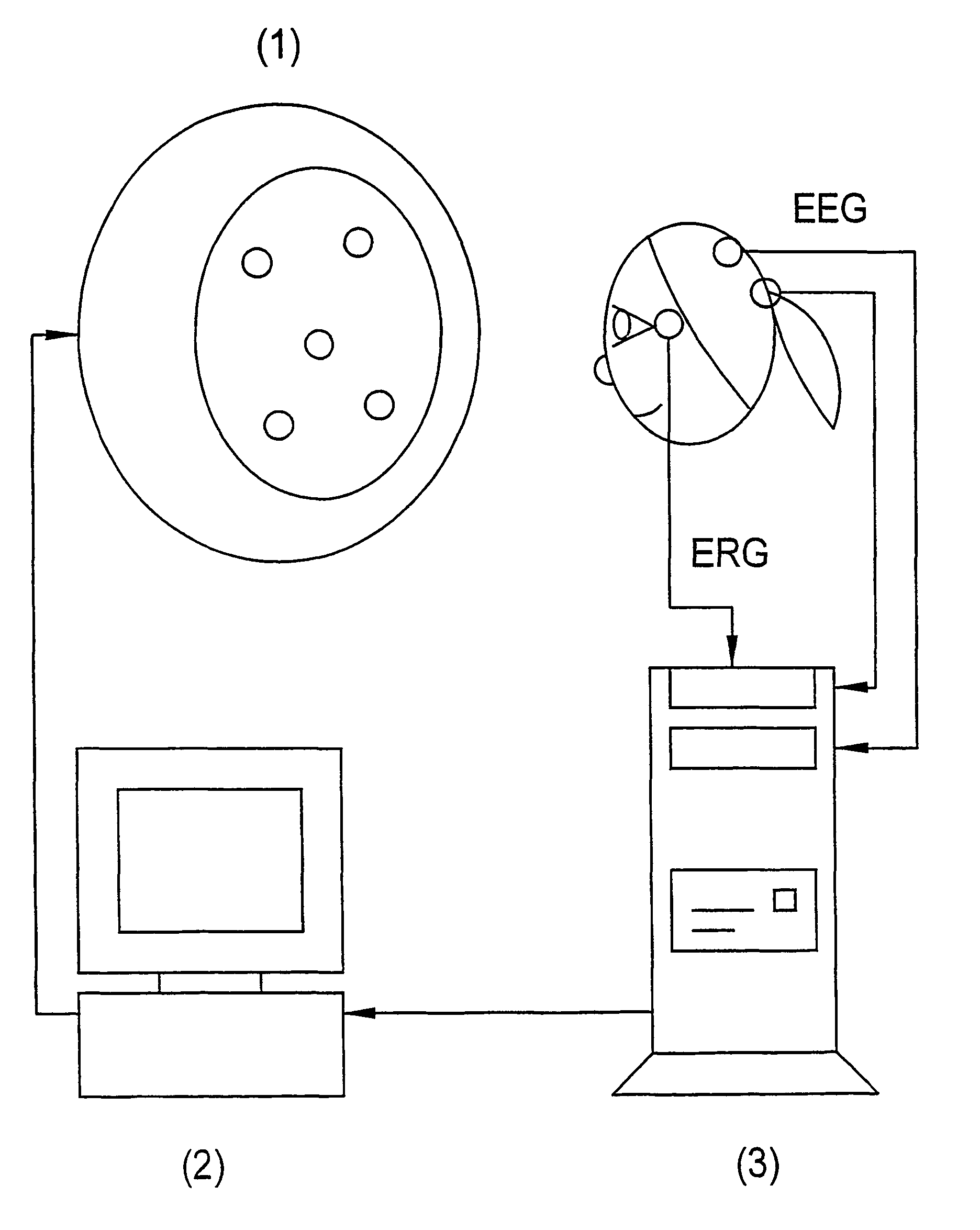
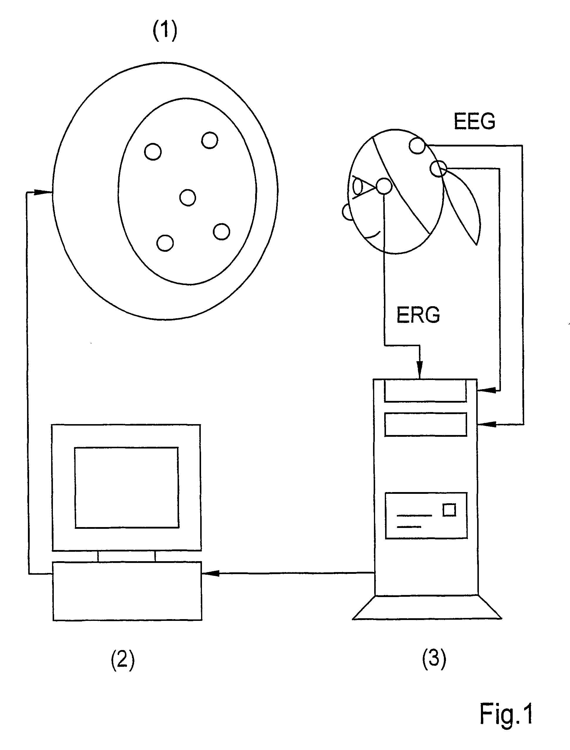
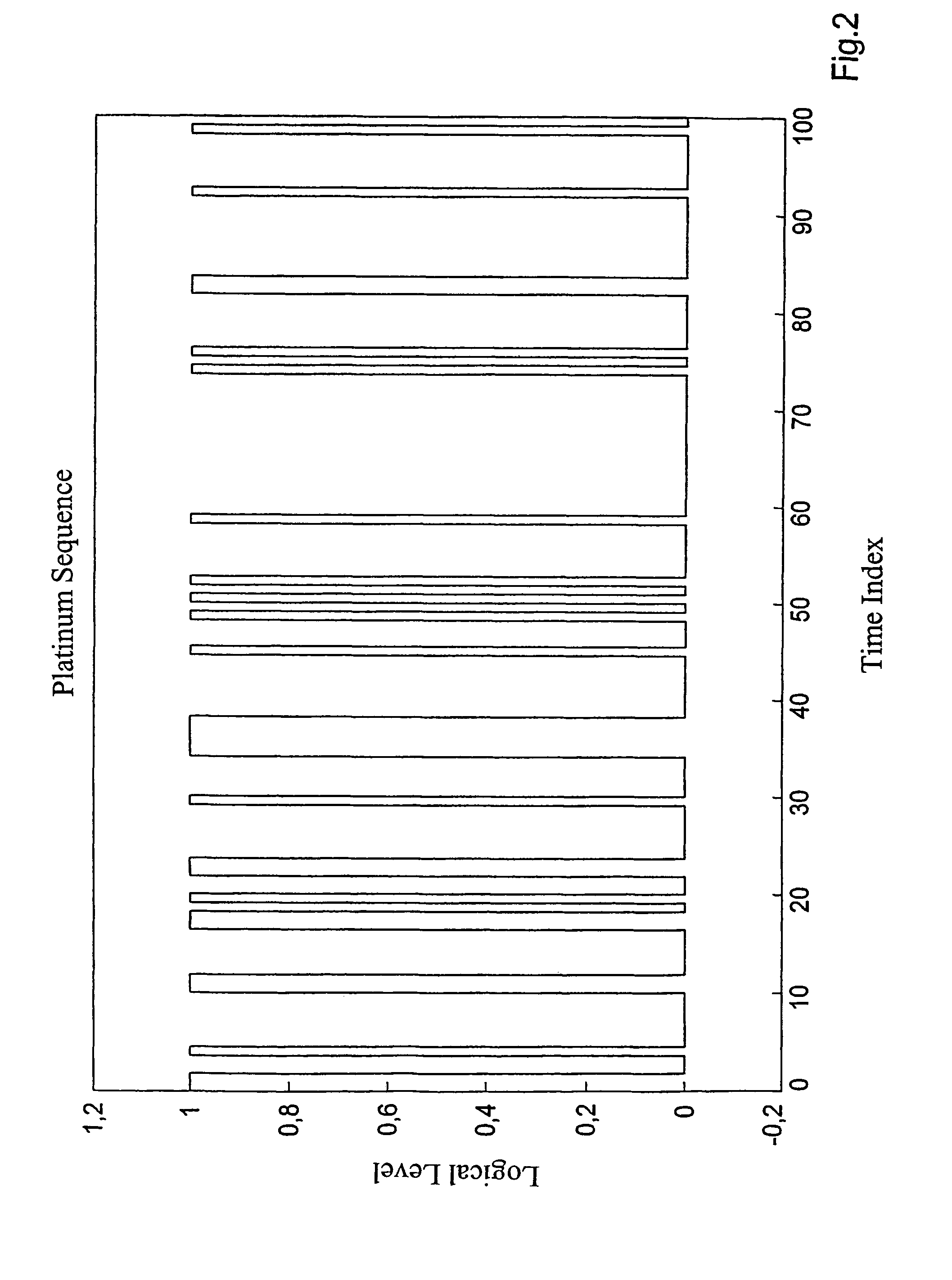
[0012]According to the invention, the object is met by using graduated light intensities in order to stimulate the visual system optically and by determining the chronological sequence and the spatial pattern of the light impulses with respect to an objective proof of responses to the stimuli. The responses to the stimuli are analyzed by means of methods of signal processing and then objectively checked for their existence with the aid of a detection test.

[0013]In one advantageous embodiments [sic] of the invention, the light source emitting the optical stimulation is controlled such that graduated light intensities can be differentiated by physi...


PUM


Abstract

A method and device for optically stimulating the visual system during static perimetry and for objectively evaluating adequate stimulus-related electrophysiological and / or magnetophysiological quantities. Light stimuli with defined parameters derived from a predetermined correlation function and from the known intensity dependence of the excitation response amplitude are presented to the observer. The excitation responses contained in the ERG and / or in the EEG / MEG are detected and processed. These excitation responses are used to determine and topographically evaluate the local sensitivity of the visual system. In one embodiment, the light sources are fixed inside a perimeter, and the excitation responses are amplified and digitized by a device, which preferably comprises an ERG / EEG measuring system and an A / D converter. To this end, the device, for the purpose of evaluating, and the light sources, for the purpose of controlling, are connected to a controlling means, preferably to a PC provided with evaluation and control software.

Description

CROSS REFERENCE TO RELATED APPLICATIONS[0001]This application claims priority to PCT Application designating the U.S. Ser. No. PCT / EP01 / 13477, filed on Nov. 21, 2001, incorporated herein by reference, which claims priority to German Application Nos. 100 58 127.7 filed Nov. 22, 2000, 101 40871.7 filed Aug. 21, 2001 and 101 46 330.8 filed Sep. 20, 2001, incorporated herein by reference.FIELD OF THE INVENTION[0002]The invention refers to a method and an apparatus for optically stimulating the visual system in accordance with the requirements of static perimeters, and for the objective evaluation of adequate stimulus-related electro- and / or magnetophysiological values.PRIOR ART[0003]Prior art stimulation systems of objective perimeters that use binary controlled light stimulators are known. To give an example, monofocal light markers of a defined intensity that light up briefly are used in perimeters in order to check the functionality of the visual system.[0004]In newer systems, multif...

Claims


Application Information

Patent Timeline
Patent Type & Authority Patents(United States)
IPC IPC(8): A61B3/02A61B3/024A61B5/0484A61B3/10
CPCA61B3/024A61B5/04842A61B3/10A61B5/378
Inventor GOTZE, ANDREASHENNING, GUNTERHUSAR, PETERBERKES, SEBASTIANSCHELLHORN, KLAUSSCHLEGELMILCH, FALK
Owner CARL ZEISS MEDITEC AG
Learn More