Device for illuminating license plate

a license plate and device technology, applied in signalling/lighting devices, vehicle components, optical signalling, etc., can solve the problems of large amount of consumed power, short life, and high cost, and achieve low luminous intensity, high luminous intensity, and directivity.

Active Publication Date: 2007-05-29
KOITO MFG CO LTD
View PDF10 Cites 14 Cited by
  • Summary
  • Abstract
  • Description
  • Claims
  • Application Information

AI Technical Summary

Benefits of technology

[0015]The present invention has various advantages. For example, according to the invention, any of lights emitted from the LED having a high directivity which gets out of the optical axis and has a low luminous intensity is reflected by the first reflector to illuminate the vicinal region of the license plate. A light transmitted along the optical axis and having a high luminous intensity is reflected by the second reflector to illuminate the distant region from the license plate. For this reason, an illuminance in the license plate can be made substantially uniform so that the whole surface of the license plate can be illuminated in a substantially equal brightness. In particular, it is possible to enhance the uniformity of the illumination by illuminating an intermediate region with a part of the light reflected by the first reflector. By forming the second reflector as a convex, it is possible to diffuse the light transmitted along the optical axis as compared with when the second reflector is formed like a concave. Thus, it is possible to enhance the utilization efficiency of a light. By supplementally illuminating the license plate with a light reflected by the third reflector, and furthermore, alight transmitted through a lens having the diffusing step, it is possible to further enhance the uniformity of the illuminance of the license plate.

Problems solved by technology

However, the incandescent bulb has a problem in that its lifetime is short and a great deal of time and labor is required to change the bulb due to a burnout.
Furthermore, the amount of consumed power is great, the burden of an on-board battery is heavy, and an installation space is large, and the degree of freedom of the design around the license plate is low.
Similarly, a technique using the incandescent bulb in JP-A-2000-168438 has such a problem.
Even if the diffusion lens step is simply provided as in JP-A-2000-168438, it is impossible to solve the problem of the nonuniform brightness.
Thus, there is a problem in that it is hard to uniformly illuminate the surface of the license plate by the LED.
However, the number of the LEDs is increased so that a cost is increased.
Furthermore, it is impossible to avoid the undesired external exposure of the LED provided around the outside of the license plate.
As a result, there is another problem in that an outer appearance is deteriorated.

Method used


Image

  • Device for illuminating license plate
  • Device for illuminating license plate
  • Device for illuminating license plate

Examples


Embodiment Construction

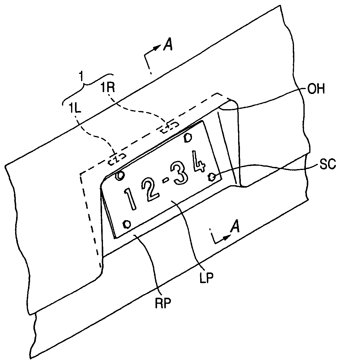
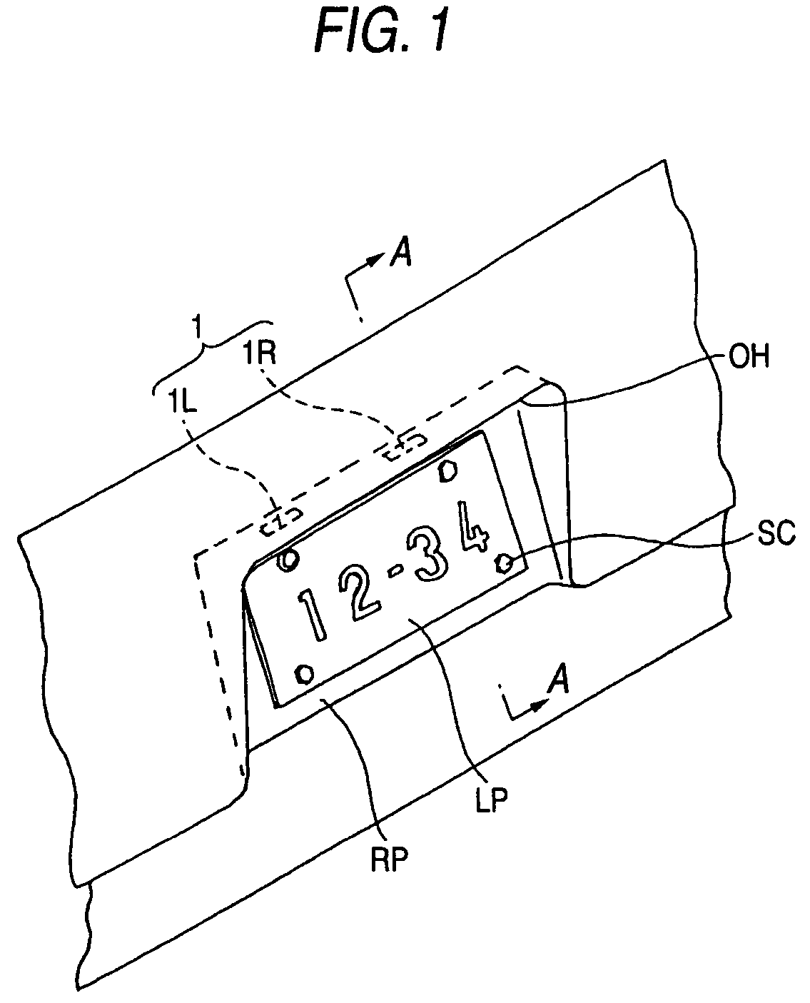
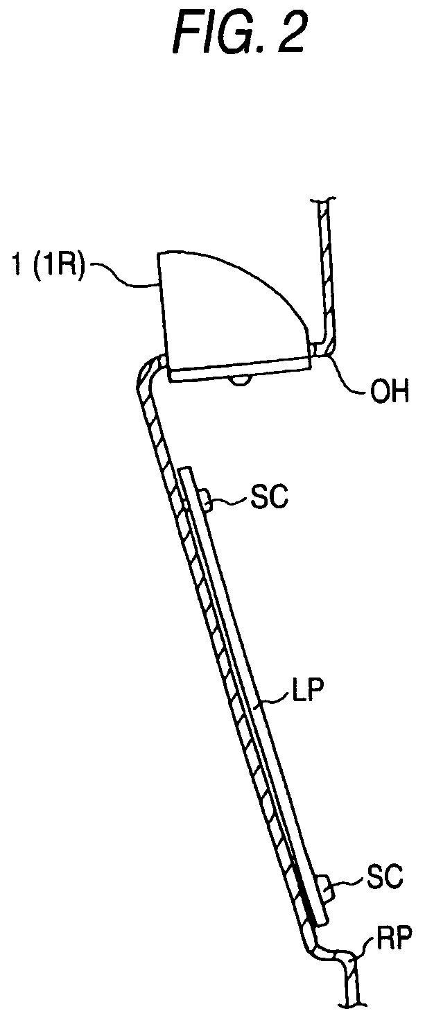
[0010]It is an object of the invention to provide a device for illuminating a license plate that can uniformly illuminate the surface of a plate via an LED disposed on one of the sides of the license plate. However, this object need not be achieved by the present invention, nor any other object. Alternatively, other objects may also be achieved by the present invention.

[0011]The invention provides a device for illuminating a license plate comprising an LED to be a light source and a reflector for reflecting a light emitted from the LED toward a surface of the license plate, wherein the reflector reflects a light along an optical axis of the LED toward a distant region from the license plate and reflects a light getting out of the optical axis of the LED toward a vicinal region of the license plate. More specifically, the reflector comprises a first reflector disposed in a region getting out of the optical axis of the LED and a second reflector disposed in a region including the opti...


PUM


Abstract

There is provided an LED as a light source and a reflector for reflecting a light emitted from the LED toward the surface of a license plate LP. The reflector has a first reflector disposed in a region getting out of the optical axis of the LED and a second reflector disposed in a region including the optical axis of the LED, and a light getting out of the optical axis and having a low luminous intensity is reflected by the first reflector to illuminate the vicinal region of the license plate and a light transmitted along the optical axis and having a high luminous intensity is reflected by the second reflector to illuminate a distant region from the license plate. An illuminance in the license plate can be made almost uniform so that the whole surface of the license plate can be illuminated in an equal brightness.

Description

[0001]The present application claims foreign priority based on Japanese Patent application no. 2004-185780, filed on Jun. 24, 2004, the contents of which is incorporated herein by reference. This foreign priority claim is being made concurrently with the filing of this application.BACKGROUND OF THE INVENTION[0002]1. Technical Field[0003]The present invention relates to a device for illuminating the license plate (information plate) of a car and more particularly to an illuminating device using an LED (a light emitting diode) for a light source.[0004]2. Background Art[0005]As a device for illuminating a license plate, a related art incandescent bulb has been used for a light source as in JP-A-2000-168438. However, the incandescent bulb has a problem in that its lifetime is short and a great deal of time and labor is required to change the bulb due to a burnout. Furthermore, the amount of consumed power is great, the burden of an on-board battery is heavy, and an installation space is...

Claims


Application Information

Patent Timeline
Patent Type & Authority Patents(United States)
IPC IPC(8): B60Q1/56
CPCB60Q1/56
Inventor KATASE, TOMOSHI
Owner KOITO MFG CO LTD
Why Eureka
Try Eureka