Antenna apparatus and method for mounting antenna
- Summary
- Abstract
- Description
- Claims
- Application Information
AI Technical Summary
Benefits of technology
Problems solved by technology
Method used
Image
Examples
first embodiment
[0028][First Embodiment]
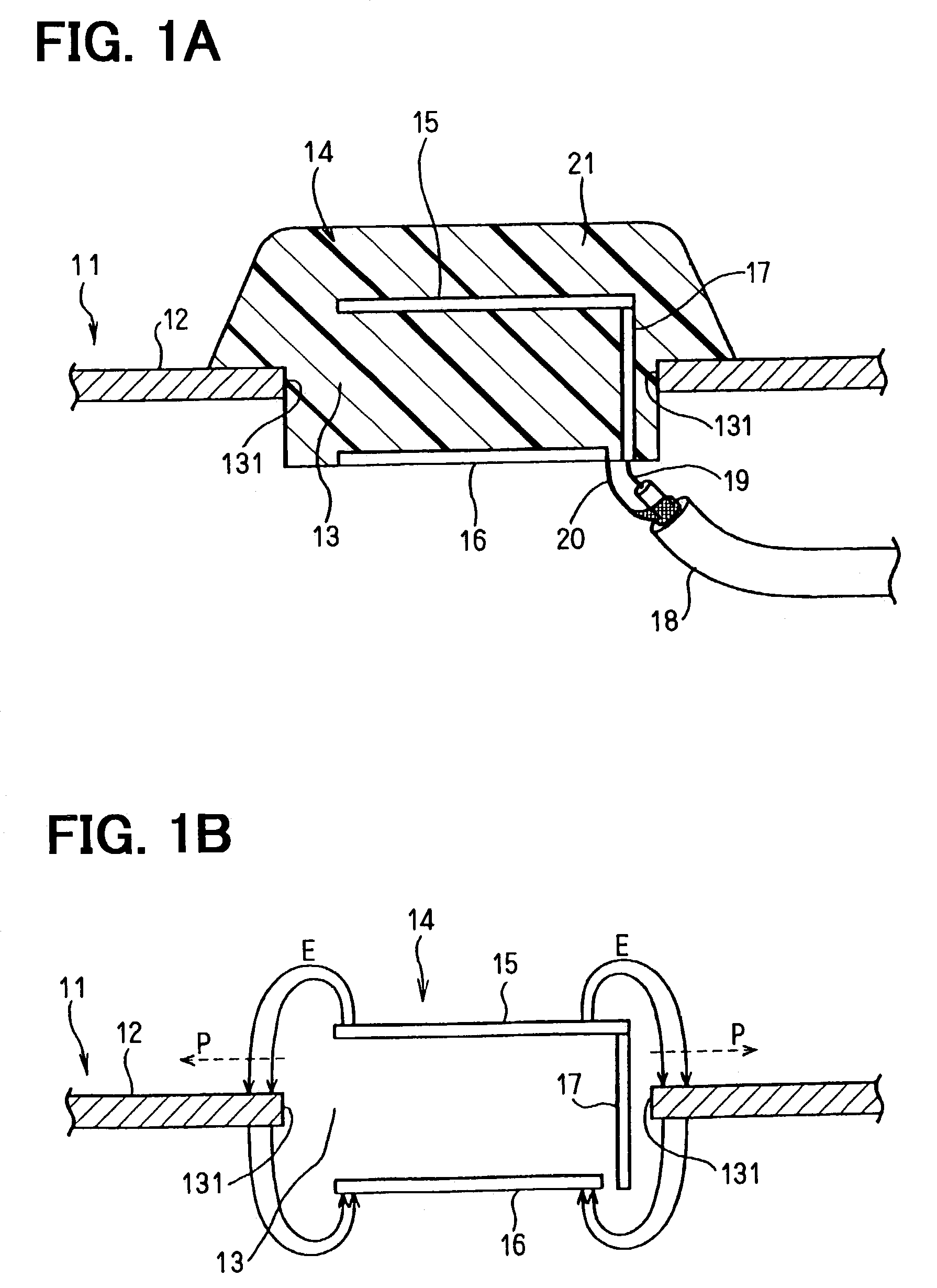
[0029]Referring to FIG. 1A, a hole 13 is provided in the body 12 of a vehicle 11 at a position, such as a roof, a trunk or a hood that is convenient for installation of a planar antenna 14. The planar antenna 14 includes a radiating element 15 and a ground plate 16. The radiating element 15 is positioned above the body 12, and the ground plate 16 is positioned below the body 12. That is, the planar antenna 14 is mounted on the vehicle 11 so that the radiating element 15 is positioned at one side of an imaginary plane inside of an internal edge 131, and the ground plate 16 is positioned at the other side of the imaginary plane.
[0030]The radiating element 15 is connected to an inner conductor 19 of a coaxial cable 18 via a feeder 17. The ground plate 16 is connected to an outer conductor 20 of the coaxial cable 18. The radiating element 15, the ground plate 16, and the feeder 17 are molded by a resin 21. The resin 21 is fixed on the body 12 by a bonding substan...
second embodiment
[0038][Second Embodiment]
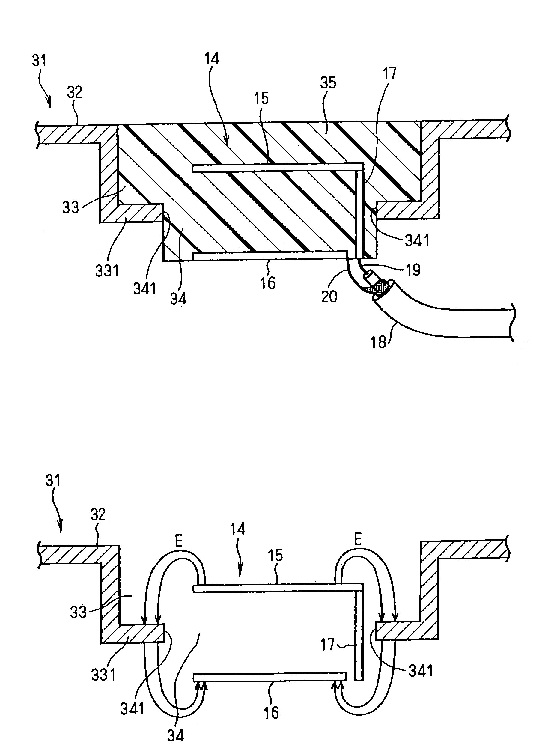
[0039]In the second embodiment, referring to FIG. 3A, a concavity 33 is formed in the body 32 of a vehicle 31, and a hole 34 is bored in a bottom plate 331 of the concavity 33. The bottom plate 331 has an internal edge 341 formed by boring the hole 34. The concavity 33 and the hole 34 are provided in the body 32 at a position, such as a roof, a trunk or a hood that is convenient for installation of the planar antenna 14 as in the first embodiment.
[0040]The radiating element 15 is positioned between an imaginary surface of the body 32 and the hole 34, and the ground plate 16 is positioned below the bottom plate 331. That is, the planar antenna 14 is mounted on the vehicle 31 so that an imaginary plane inside of the internal edge 341 is located between the radiating element 15 and the ground plate 16. The radiating element 15, the ground plate 16, and the feeder 17 are molded by a resin 35.
[0041]Referring to FIG. 3B, the electric lines of force formed by the e...
third embodiment
[0046][Third Embodiment]
[0047]Referring to FIG. 5A, in the third embodiment, by comparison with the second embodiment, the planar antenna 14 has a metal plate 41 and an electrical connection element 42. The metal plate 41 is positioned between the radiating element 15 and the ground plate 16. The electrical connection element 42 is positioned between the metal plate 41 and the bottom plate 331 of the concavity 33. The metal plate 41 is connected electrically to the body 32 of the vehicle 31 via the electrical connection element 42. The electrical connection element 42 is made of a metal or a dielectric, such as a resin, for protecting the antenna 14, and rubber packing for waterproofing the antenna 14.
[0048]In addition, the planar antenna 14 has a metal element 44 that electrically connects the metal plate 41 to the ground plate 16. As, a result, the body 32, the metal plate 41, and the ground plate 16 are at the same electric potential. A resin 45 molds the radiating element 15, th...
PUM
 Abstract
Description
Claims
Application Information
 - R&D
- Intellectual Property
- Life Sciences
- Materials
- Tech Scout
- Unparalleled Data Quality
- Higher Quality Content
- 60% Fewer Hallucinations
Browse by: Latest US Patents, China's latest patents, Technical Efficacy Thesaurus, Application Domain, Technology Topic, Popular Technical Reports.
© 2025 PatSnap. All rights reserved.Legal|Privacy policy|Modern Slavery Act Transparency Statement|Sitemap|About US| Contact US: help@patsnap.com


