High-precision linear optocoupler structure with adjustable transmission gain and coupling method thereof

A transmission gain, linear optocoupler technology, applied in electrical components, electrical solid devices, circuits, etc., can solve the problems of inability to meet the needs of analog signal transmission, large transmission gain deviation, insufficient transmission accuracy, etc., and achieve consistent optimized spectral response. performance and quantum efficiency, improved precision and nonlinearity, and the effect of optimizing process conditions

Pending Publication Date: 2021-11-30
THE 44TH INST OF CHINA ELECTRONICS TECH GROUP CORP
View PDF0 Cites 0 Cited by
  • Summary
  • Abstract
  • Description
  • Claims
  • Application Information

AI Technical Summary

Problems solved by technology

[0004] At present, among the major foreign manufacturers of linear optocoupler devices, typical linear optocoupler products such as the IL300 series of the American VISHAY company, the HCNR200 / 2001 of the American Agilent company, and the TIL300 / 300A series of the American TI company are all plastic packaged device products. , Plastic mold, internal structure and photodetector batch differences, the transmission gain and distribution range of each device is relatively large, and the transmission gain deviation is greater than 5%. For example, the transmission gain of HCNR200 is 0.85-1.15, and the transmission gain of HCNR201 is 0.93 ~1.07, the transmission gain of IL300 is 0.56~1.65, the transmission gain of TIL300 is 0.75~1.25, the transmission gain of TIL300A is 0.9~1.1, and the internal glue filling of the device leads to a large deviation in transmission gain under high and low temperature environments, which makes it difficult to use in actual circuits. Each linear optocoupler needs to be configured with different high-precision debugging resistors to solve the problem of insufficient transmission accuracy. It is relatively complicated to use. In addition, the transmission gain cannot be adjusted according to the actual use of the circuit, which cannot meet the needs of flexible adjustment of analog signal transmission.

Method used


Image

  • High-precision linear optocoupler structure with adjustable transmission gain and coupling method thereof
  • High-precision linear optocoupler structure with adjustable transmission gain and coupling method thereof
  • High-precision linear optocoupler structure with adjustable transmission gain and coupling method thereof

Examples


Embodiment 1

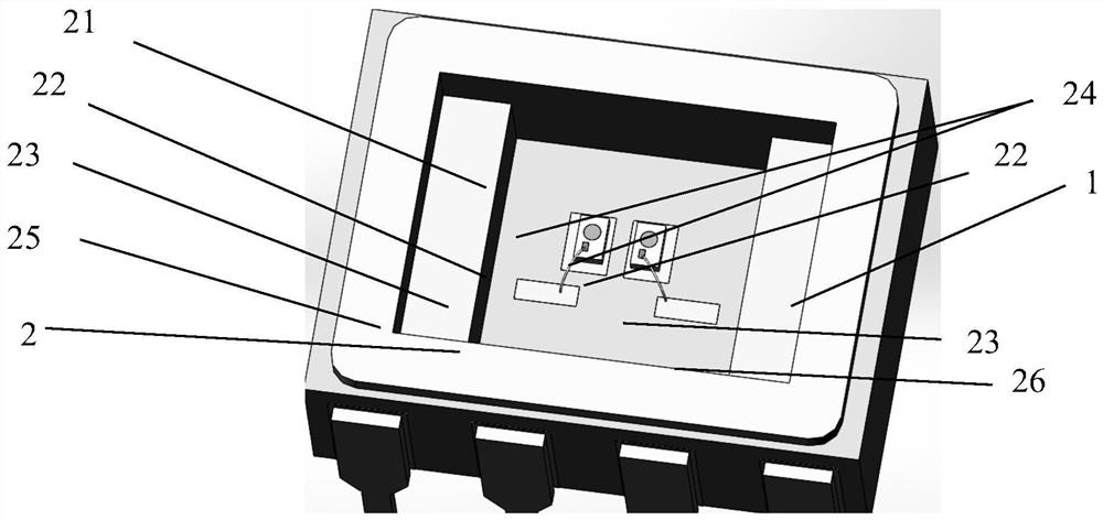
[0046] In this embodiment, a high-precision linear optocoupler structure with adjustable transmission gain, such as figure 1 , including a base 1, a photosensitive integrated board 2, a cover plate 3 and a packaging shell;

[0047] The inside of the base 1 is provided with a groove, which is used to place the photosensitive integrated board 2 and the cover plate 3;

[0048] Such as figure 1 , the photosensitive integrated board 2 includes: a base plate 21, two metal pads 22, two gold conduction strips 23, two photodetector chips 24, and two ceramic steps 24; the ceramic steps 25, 26 are respectively arranged on the base plate At the left and right ends of 21, the upper surface of the ceramic steps is gold-plated and connected to the corresponding metal outer pins of the package shell; the gold pad 22 and the gold conductive strip 23 are all arranged on the upper part of the upper plane of the bottom plate 21, and the two Two gold pads and two gold conduction strips are respe...

Embodiment 2

[0067] In this embodiment, a coupling method of a high-precision linear optocoupler structure with adjustable transmission gain is proposed, including:

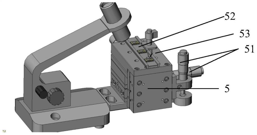
[0068] Step 1: If image 3 , the micro-motion table 5 is set, and the micro-motion table can realize three axial displacements of X, Y, and Z through the adjustment knob 51;

[0069] Step 2: set special groove socket (52) on the micro-movement table 5, each groove socket is provided with a metal card slot, can clamp the package shell, the metal outer pin of package shell 4 passes through the metal card slot one one-to-one connection;

[0070] Step 3: Install the packaging shell (not yet hermetically sealed) including the base 1 and the photosensitive integrated board 2 in the recessed socket (52), the recessed socket (52) has built-in electrical leads, and the metal of the packaged shell can be realized. The electrical connection of the outer pins also realizes the electrical connection of each electrode of the photodetecto...


PUM


Abstract

The invention relates to the technical field of linear optoelectronic isolation devices, in particular to a high-precision linear optocoupler structure with adjustable transmission gain and a coupling method thereof, and the high-precision linear optocoupler structure with adjustable transmission gain comprises a base, a photosensitive integrated board, a cover plate and a packaging shell; the packaging shell carries out airtight packaging on the base, the photosensitive integrated board and the cover plate; a groove is formed in the base and is used for placing the photosensitive integrated board and the cover plate; the photosensitive integrated board comprises a base plate, two metal pads, two gold conduction bands, two photoelectric detector chips, a first ceramic step and a second ceramic step; the cover plate comprises a fixed plate, a short gold conduction band, a long gold conduction band, two transverse semicircular gaps, two longitudinal semicircular gaps and an LED chip; and the technical problem that the transmission gain of the linear optocoupler cannot be flexibly adjusted is effectively solved, and the transmission precision is improved.

Description

technical field [0001] The invention relates to the technical field of linear optoelectronic isolation devices, in particular to a high-precision linear optocoupler structure with adjustable transmission gain and a coupling method thereof. Background technique [0002] In the field of signal isolation transmission, because photoelectric isolation uses light signals as the transmission medium through light-emitting devices and photosensitive devices, it has many advantages such as one-way transmission, strong anti-interference ability, long service life, and no contact. It is widely used in various measurement systems. use. [0003] Among them, in the field of optical isolation transmission of analog signals, the more commonly used circuits are composed of linear optocouplers, feedback circuits and transimpedance amplifier output circuits. The transmission gain of analog signals depends on the transmission gain of linear optocoupler devices, while the linear optocoupler devic...

Claims


Application Information

Patent Timeline
Patent Type & Authority Applications(China)
IPC IPC(8): H01L25/16H01L23/04H01L33/00H01L33/10H01L33/38H01L31/0216H01L31/105H01L21/50
Inventor 胡锐兴张广涵丁鹏欧熠龚磊张浩张怡吴冬石云莲
Owner THE 44TH INST OF CHINA ELECTRONICS TECH GROUP CORP
Why Eureka
Try Eureka