Method of preconfiguring optical protection trails in a mesh-connected agile photonic network

a photonic network and agile technology, applied in the field of optical telecommunications networks, can solve the problems that traditional traffic protection schemes (electrical) are not directly applicable to optical switching, and the linear topology cannot protect against single fiber link failure, so as to reduce the number of protect wavelengths and optimize the bandwidth utilization across the network

Active Publication Date: 2007-05-29
ALCATEL-LUCENT USA INC
View PDF5 Cites 20 Cited by
  • Summary
  • Abstract
  • Description
  • Claims
  • Application Information

AI Technical Summary

Benefits of technology

[0016]According to another aspect, the invention is directed to a method of automatically re-routing a connection demand along a protect trail whenever an optical working path is affected by a fault. The method comprises: generating an optical-layer cycle that has a plurality of successive optical paths; for each optical path on the cycle, identifying the reminder of the optical paths on the cycle as an optical protect trail; and pre-configuring a plurality of protection switching scenarios by associating each optical path on the cycle with a respective optical protect trail for enabling fast traffic recovery when any of the optical working paths fails.
[0018]An advantage of the mesh routing method of this invention is that it optimizes the bandwidth utilization across the network by reducing the number of protect wavelengths.

Problems solved by technology

A linear topology can only protect against single fiber link failures.
Since the operation of the agile network differs from that of pt—pt networks, traditional traffic protection schemes (electrical) are not directly applicable to optical switching.

Method used


Image

  • Method of preconfiguring optical protection trails in a mesh-connected agile photonic network
  • Method of preconfiguring optical protection trails in a mesh-connected agile photonic network
  • Method of preconfiguring optical protection trails in a mesh-connected agile photonic network

Examples


Embodiment Construction

[0034]The following description is of a preferred embodiment by way of example only and without limitation to combination of features necessary for carrying the invention into effect.

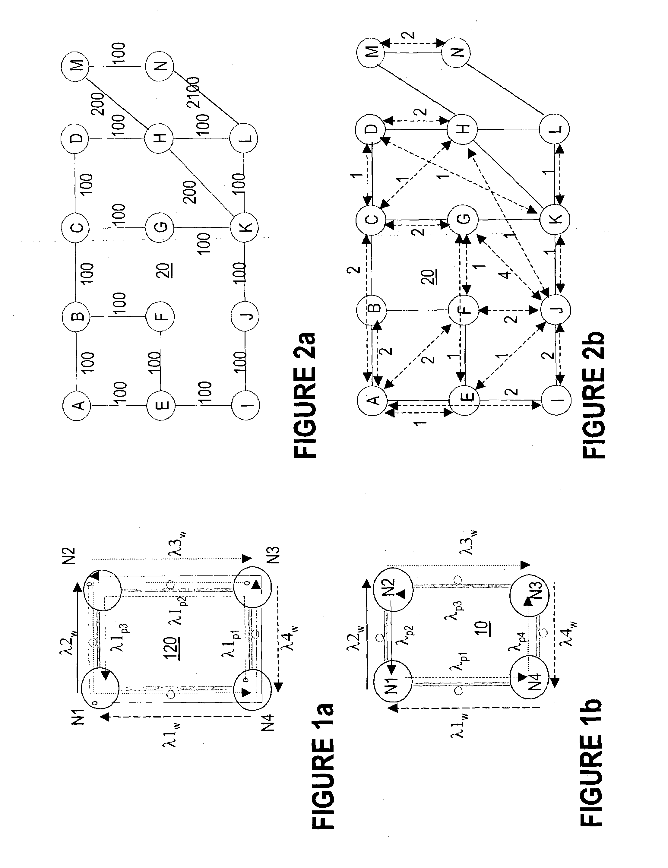
[0035]FIG. 1a illustrates a simplified example of an agile photonic network APN 20 with four nodes N1–N4, and four working connections carried by channels λ1w–λ4w.

[0036]The term “network node” or “node” refers to a node that performs optical switching and add / drop, and may also perform signal regeneration. FIG. 1a illustrates only the end-nodes for each optical connection and not the intermediate switching nodes.

[0037]The term “optical path” refers to the path of a channel (wavelength) from a node where the channel is added, to a node where the channel is dropped. The term “trail” refers to an end-to-end route set-up in response to a connection demand. An optical trail carries the user traffic from the source node to the destination node and may be established along one or more optical paths, according ...


PUM

PropertyMeasurementUnit
distanceaaaaaaaaaa
distanceaaaaaaaaaa
distanceaaaaaaaaaa

Abstract

The method of pre-configuring the optical protect paths in an agile photonic network establishes a protection trail for each optical working path that may be set-up in the network. The pre-configuration is based on building an electrical layer (EXC) graph that takes into account all the connection demands in the network, and finding on this EXC graph a plurality of cycles. Next, the EXC cycles are validated at the optical layer, and are further validated against constraints. The method attempts to find an optimal cycles solution, without exhausting all possible variants.

Description

RELATED US PATENT APPLICATIONS[0001]U.S. patent application Ser. No. 10 / 061,623 “Routing Cycles for Wavelength Switched Optical Networks” (Slezak et al.), filed Feb. 1, 2002 and assigned to Innovance Inc.[0002]U.S. patent application Ser. No. 09 / 909,265, entitled “Wavelength Routing and Switching Mechanism for a Photonic Transport Network”, Smith et al., filed Jul. 19, 2001, assigned to Innovance Networks.[0003]These patent applications are incorporated herein by reference.FIELD OF THE INVENTION[0004]The invention resides in the field of optical telecommunications networks, and is directed in particular to a method for pre-configuring protection trails in a mesh-connected agile photonic network.BACKGROUND OF THE INVENTION[0005]A linear topology can only protect against single fiber link failures. Thus, a “1:1” linear system has an equal number of working and protection links; a “1:N” linear system has N working channels and one shared protection channel.[0006]Lately, rings have beco...

Claims


Application Information

Patent Timeline
Patent Type & Authority Patents(United States)
IPC IPC(8): G02F1/00
CPCH04J14/0227H04J14/0284H04J14/0287H04J14/0295H04L45/22H04L45/28H04Q11/0062H04J14/0241H04Q2011/0073H04Q2011/0081
Inventor SLEZAK, JAMESFRIESEN, GREG PETERROORDA, PETER DAVID
Owner ALCATEL-LUCENT USA INC
Why Eureka
Try Eureka