Expandable liner hanger system and method

a liner and extension technology, applied in the direction of fluid removal, earthwork drilling and mining, borehole/well accessories, etc., can solve the problems of affecting the setting operation, difficult retrieval, and other liner hangers and running tools cannot perform conventional cementing operations, etc., to achieve the effect of high reliability and construction more economically

Active Publication Date: 2007-06-05
TIW
View PDF7 Cites 93 Cited by
  • Summary
  • Abstract
  • Description
  • Claims
  • Application Information

AI Technical Summary

Benefits of technology

[0019]An advantage of the invention is that the liner hanger may be constructed more economically than other prior art liner hangers. The assembly consists of few components. A related advantage is that many of the components of the assembly, such as slips and packer seals, may be commercially available in accordance with various downhole conditions.
[0020]Another advantage of the invention is that the system for forming a liner hanger may utilize conventional components each with a high reliability. Existing personnel with a minimum of training may reliably use the liner hanger system according to this invention since the invention relies upon well known surface operations to reliably form the liner hanger.

Problems solved by technology

Liner hangers with multiple parts pose a significant liability when one or more of the parts becomes loose in the well, thereby disrupting the setting operation and making retrieval difficult.
Other liner hangers and running tools cannot perform conventional cementing operations through the running tool before setting the liner hanger in the well.
Other liner hangers have problems supporting heavy liners with the weight of one million pounds or more.
Some liner hangers successfully support the liner weight, but do no reliably seal with the casing string.
After the liner hanger is set in the well, high fluid pressure in the annulus between the liner and the casing may blow by the liner hanger, thereby defeating its primary purpose.
Other liner hangers are not able to obtain burst and / or collapse characteristics equal to that of the casing.
Prior art designs relied upon expansion of the tubular anchor from an elastic state in which the steel lost its elasticity or memory, resulting in relaxation of the energy necessary to maintain the liner hanger at the fully expanded diameter, thus leading to a failure of sealing and suspension supporting capability.
Another significant problem with some liner hangers is that the running tool cannot be reliably disengaged from the set liner hanger.
Another problem with liner hanger technology concerns the desirability to rotate the liner with the work string in the well, then disengage from the work string when the liner hanger has been set to retrieve the running tool from the well.

Method used


Image

  • Expandable liner hanger system and method
  • Expandable liner hanger system and method
  • Expandable liner hanger system and method

Examples


Embodiment Construction

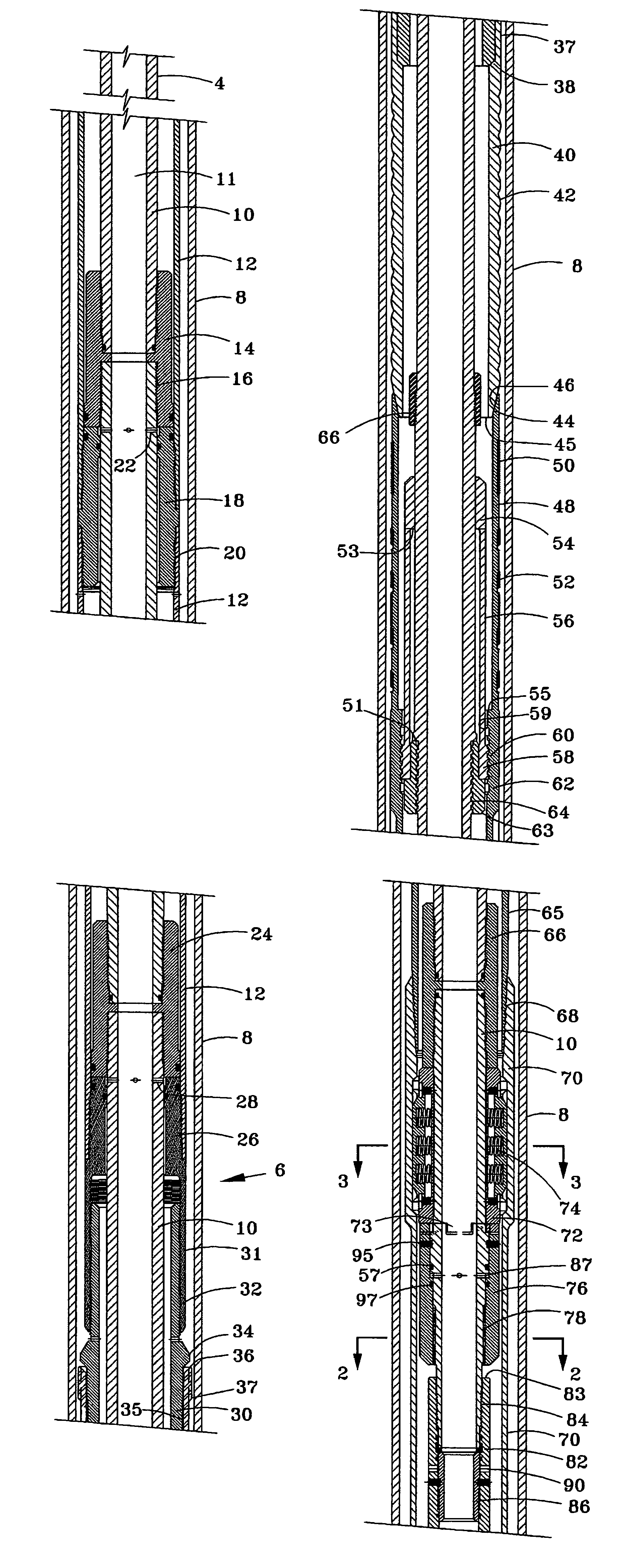
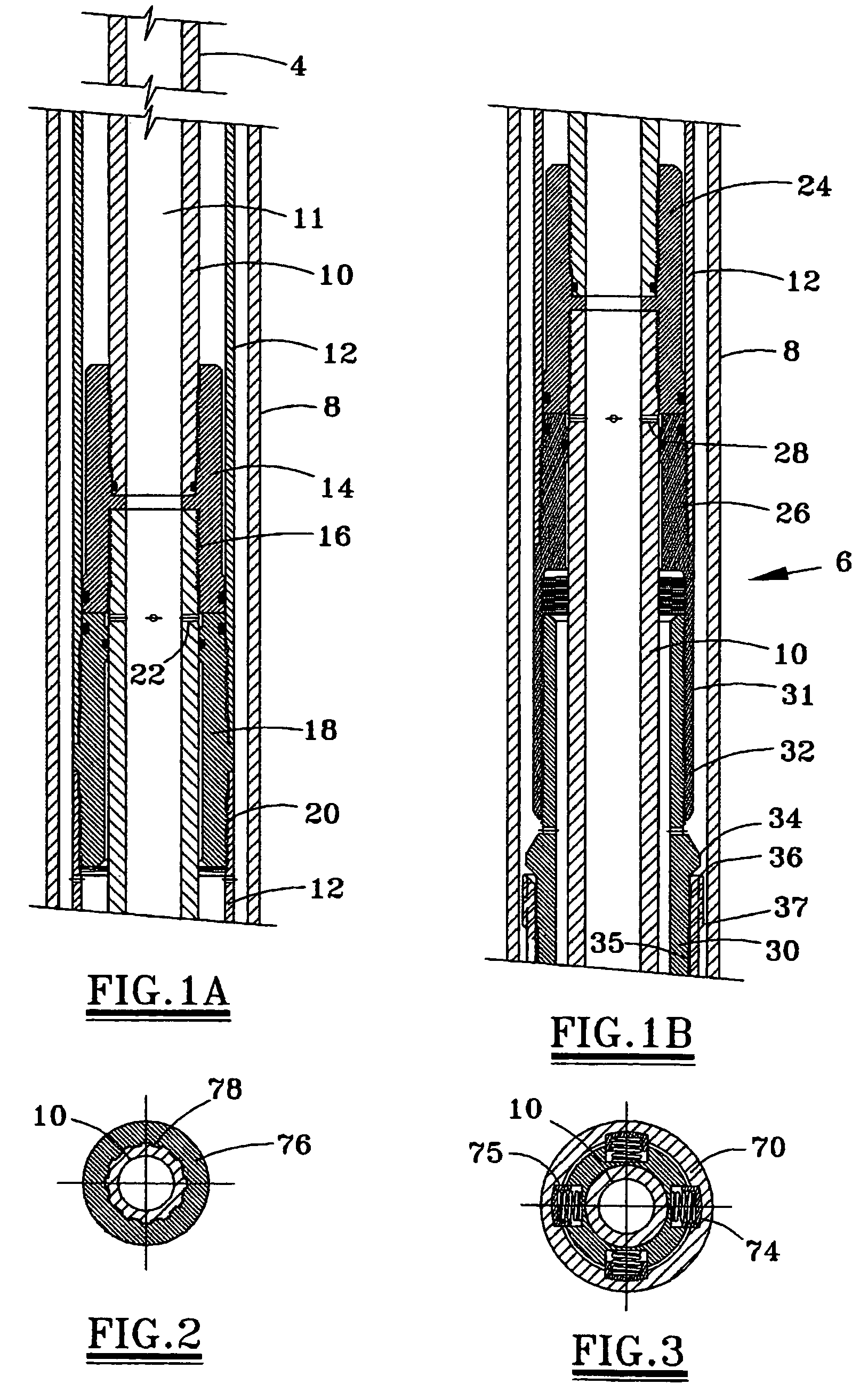
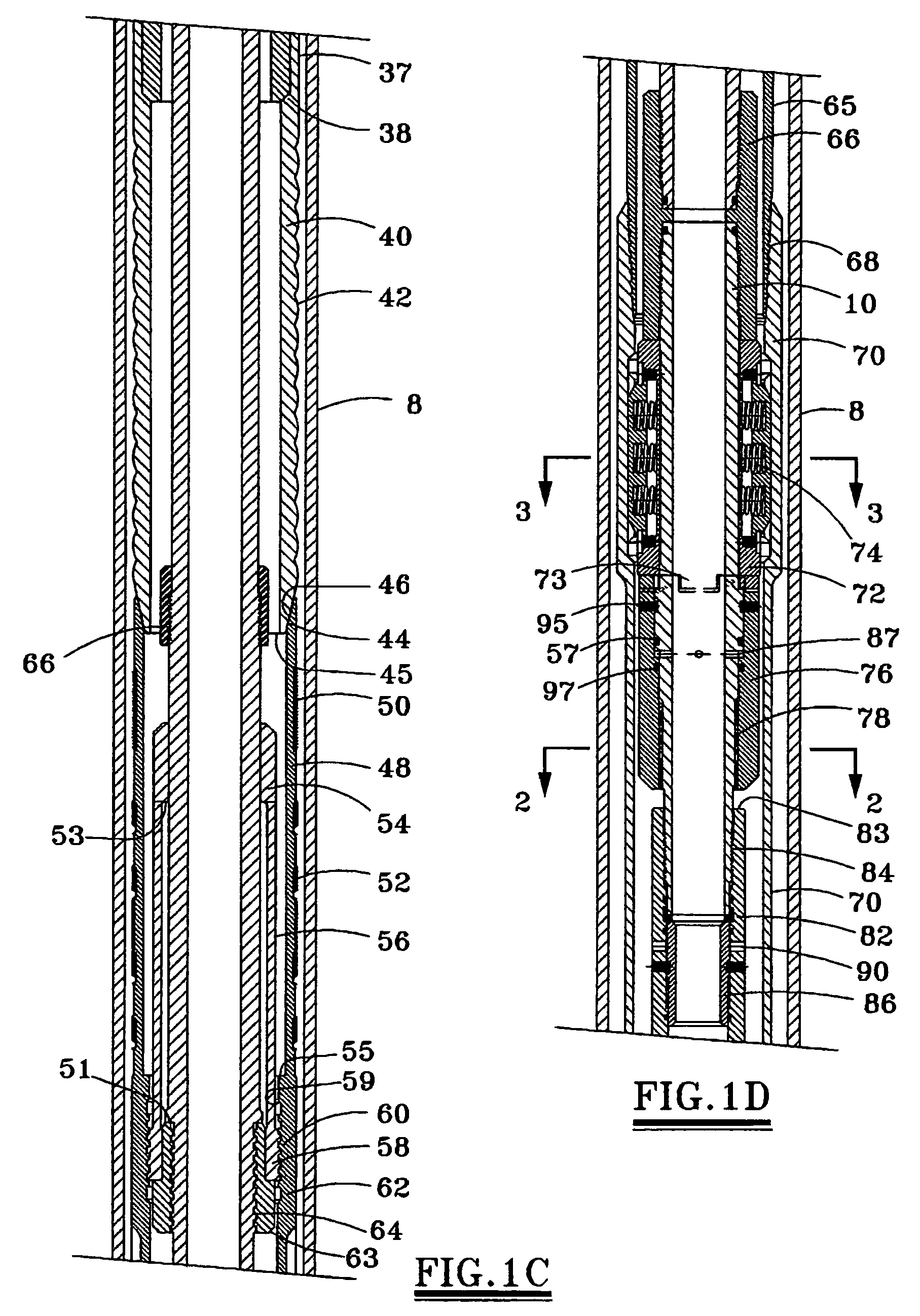
[0030]A liner may be conveyed into the well to the desired setting or suspension depth by a drill pipe or work string connected to a multi-stage, double action hydraulic setting and releasing tool (running tool) that furnishes the necessary forces to expand the liner hanger into engagement with the casing. The running tool may be constructed of sufficiently high strength steel to support the weight of the liner as it is run into the well and to provide the necessary force to expand the liner. Additionally, the running tool has a sufficiently large internal bore in its central mandrel to enable passage and displacement of cement for cementing the liner within the well bore.

[0031]A feature of the present invention is that the liner hanger and setting tool may be furnished with an interlocking releasable mechanism to prevent rotation between the running tool mandrel and the liner to permit drilling of the liner into the well, while allowing relative rotation between the running tool ma...


PUM


Abstract

The liner hanger assembly seals with casing 8 and supports a liner 98 within a well. The tubular liner hanger 48 and a tubular expander 40 may be position downhole on a running tool at a desired depth along the casing string 8. An actuator assembly 6 may forcably move the tubular expander 40 into the tubular hanger, expanding the liner hanger to seal and secure the hanger against the casing string 8. After the running tool has been removed, a seal nipple may be sealed to the sealing sleeve of the tubular expander. A selectively releasable clutch 73 is provided for allowing rotation of the liner to rotate the liner with the running tool, and thereafter to disengage and release the running tool from the set liner hanger.

Description

FIELD OF THE INVENTION[0001]The present invention relates to downhole tools and techniques for hanging a liner in a well. More particularly, the invention relates to forming an expandable liner hanger for grippingly engaging a casing string to support the liner in the well.BACKGROUND OF INVENTION[0002]Various types of liner hangers have been proposed for hanging a liner from a casing string in a well. Most liner hangers are set with slips activated by the liner hanger running tool. Liner hangers with multiple parts pose a significant liability when one or more of the parts becomes loose in the well, thereby disrupting the setting operation and making retrieval difficult. Other liner hangers and running tools cannot perform conventional cementing operations through the running tool before setting the liner hanger in the well.[0003]Other liner hangers have problems supporting heavy liners with the weight of one million pounds or more. Some liner hangers successfully support the liner ...

Claims


Application Information

Patent Timeline
Patent Type & Authority Patents(United States)
IPC IPC(8): E21B23/00E21B43/10
CPCE21B43/106E21B43/103
Inventor BRADDICK, BRITT O.
Owner TIW
Why Eureka
Try Eureka