High-pressure discharge lamp with improved ignition quality and ignition device for a gas discharge lamp
- Summary
- Abstract
- Description
- Claims
- Application Information
AI Technical Summary
Benefits of technology
Problems solved by technology
Method used
Image
Examples
first embodiment
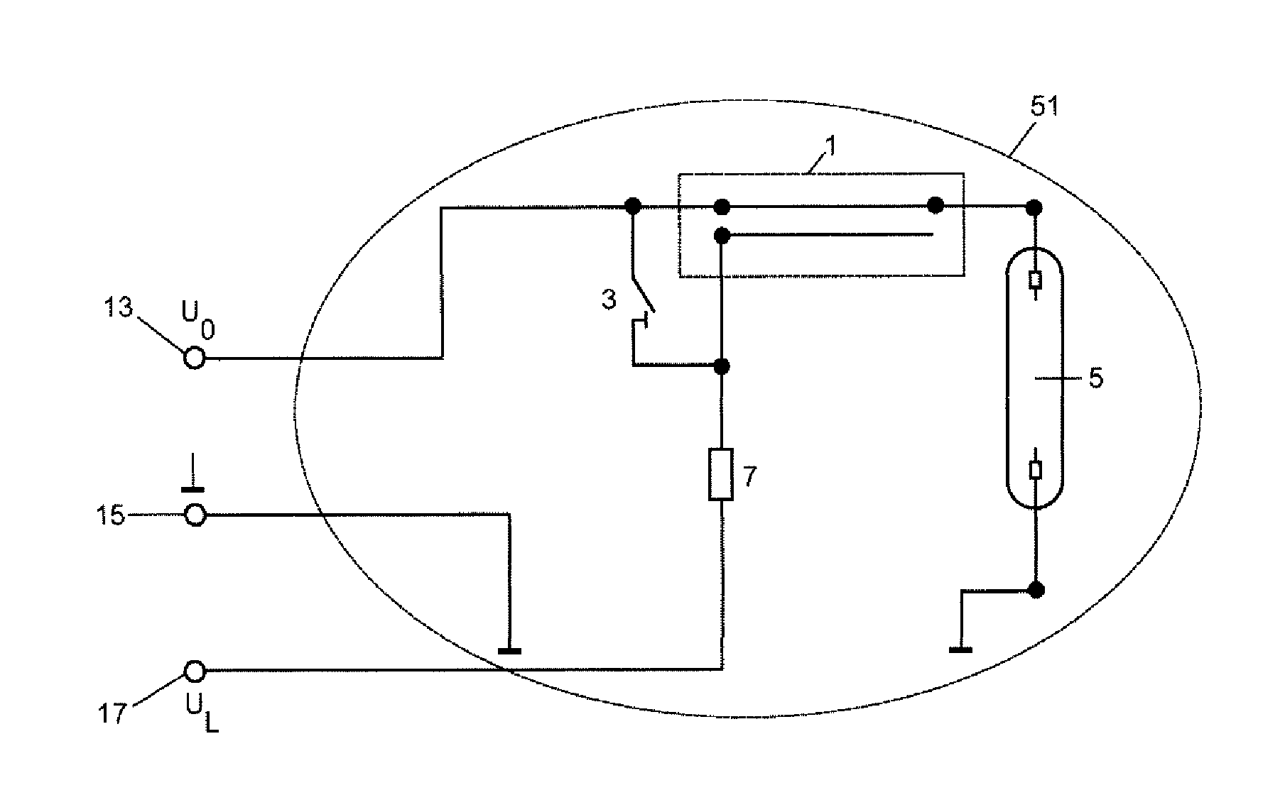
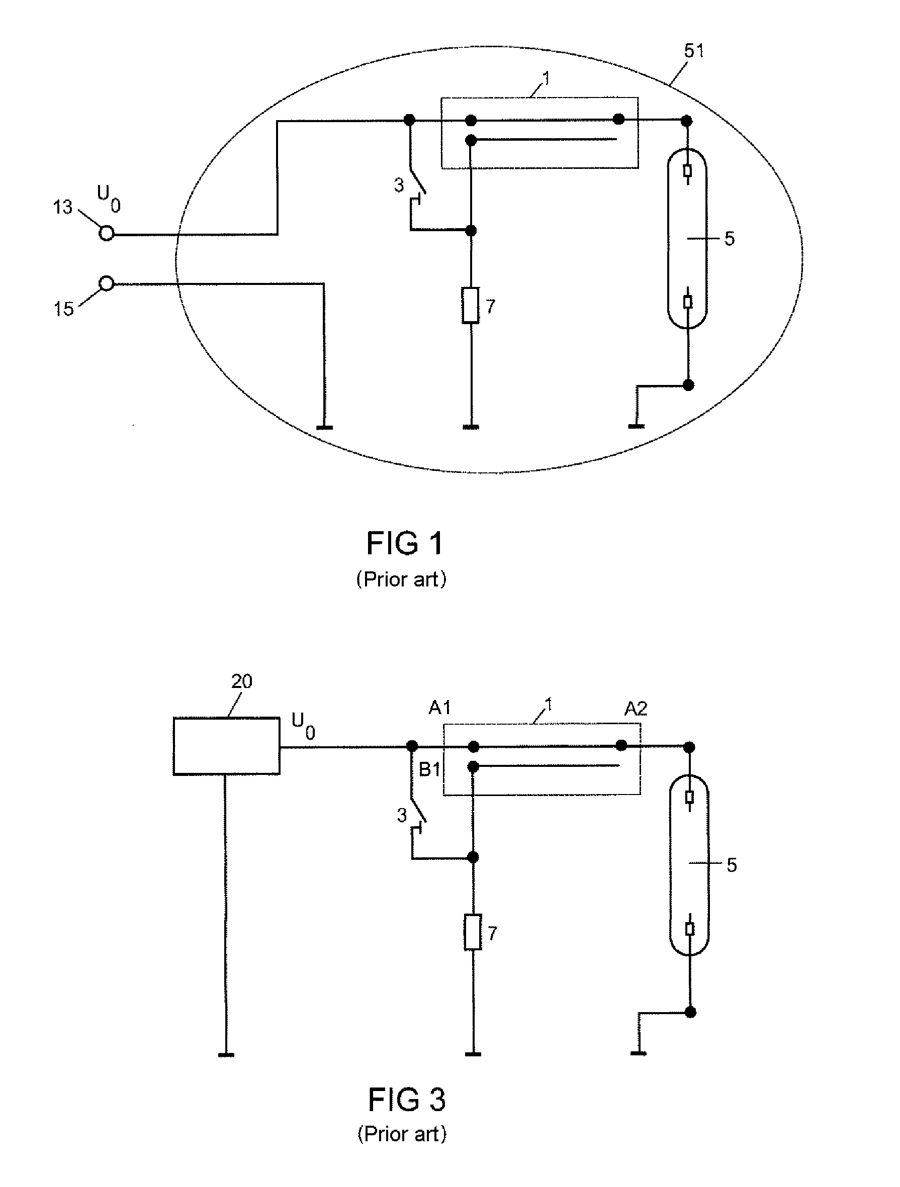
[0028]In the first embodiment, as may be seen in FIG. 4, a second charging voltage 17 in addition to the known open-circuit voltage is generated by the operating apparatus and fed to the ignition apparatus with the spiral pulse generator according to the invention. The charging voltage UL (17) preferably has an opposite sign to the open-circuit voltage U0 (13). The voltage applied to the spiral pulse generator therefore reaches U0-UL, and in the method according to the invention is therefore higher by the magnitude of UL than the charging voltage according to the prior art. FIG. 4 shows a gas discharge lamp according to the invention, in which the discharge tube 5 and the spiral pulse generator 1 with its circuitry are fitted in the outer bulb 51 of the gas discharge lamp. Although three voltage potentials must be fed into the lamp in this embodiment, all three potentials vary at a comparatively low voltage level so that the feed-throughs into the lamp bulb are loaded less.
second embodiment
[0029]If the gas discharge lamp is furthermore to be produced with two electrical leads, then the increased charging voltage may be generated from the open-circuit voltage of the operating apparatus. Depending on whether the open-circuit voltage of the operating apparatus is a DC voltage or an AC voltage, various methods may be envisaged.
[0030]The second embodiment relates to an embodiment in which an AC voltage is provided as the open-circuit voltage by the operating apparatus. FIG. 5 shows the circuit diagram of a voltage multiplier circuit. This circuit is also known as a Villard cascade or a Cockcroft-Walton generator. A stage of the cascade circuit respectively consists of two capacitors 31 and 33 and two diodes 35 and 37, which are respectively connected in the known manner. At each stage, this cascade circuit doubles the voltage. The output voltage is therefore given as: UV=2*i*U0. After ignition of the lamp, the lamp voltage, which is generally much less than the open-circui...
third embodiment
[0033]In the third embodiment, the type of open-circuit voltage is not important for the function of the ignition mechanism. At the same time, very high ignition voltages can be produced which make hot reignition of the lamp readily possible. In the third embodiment, as represented in FIG. 7, two spiral pulse generators are connected in succession. The first spiral pulse generator 11 is supplied in a manner known per se by the open-circuit voltage U0 of the operating apparatus. The switching element 31, preferably a spark gap, is dimensioned so that the threshold voltage lies just below the open-circuit voltage U0. The first spiral pulse generator therefore generates an output voltage of: USPG1=2×n1×U0×n1. The output voltage pulses are sent through an arbitrarily biased diode path 9 and a charging resistor 7 to the input of the second spiral pulse generator 1. The second spiral pulse generator 1 is therefore charged slowly by a multiplicity of pulses of the first spiral pulse genera...
PUM
 Abstract
Description
Claims
Application Information
 - R&D
- Intellectual Property
- Life Sciences
- Materials
- Tech Scout
- Unparalleled Data Quality
- Higher Quality Content
- 60% Fewer Hallucinations
Browse by: Latest US Patents, China's latest patents, Technical Efficacy Thesaurus, Application Domain, Technology Topic, Popular Technical Reports.
© 2025 PatSnap. All rights reserved.Legal|Privacy policy|Modern Slavery Act Transparency Statement|Sitemap|About US| Contact US: help@patsnap.com


