Tool and method for forming a lug hole

a tool and lug hole technology, applied in the field of vehicle wheels, can solve the problems of requiring a great deal of time and effort to form the lug hol

Inactive Publication Date: 2007-06-05
HAYES LEMMERZ INT
View PDF41 Cites 29 Cited by
  • Summary
  • Abstract
  • Description
  • Claims
  • Application Information

AI Technical Summary

Problems solved by technology

Because a vehicle wheel typically includes five lug holes, it is apparent that a great deal of time and effort is required to form the lug holes.

Method used


Image

  • Tool and method for forming a lug hole
  • Tool and method for forming a lug hole
  • Tool and method for forming a lug hole

Examples


Embodiment Construction

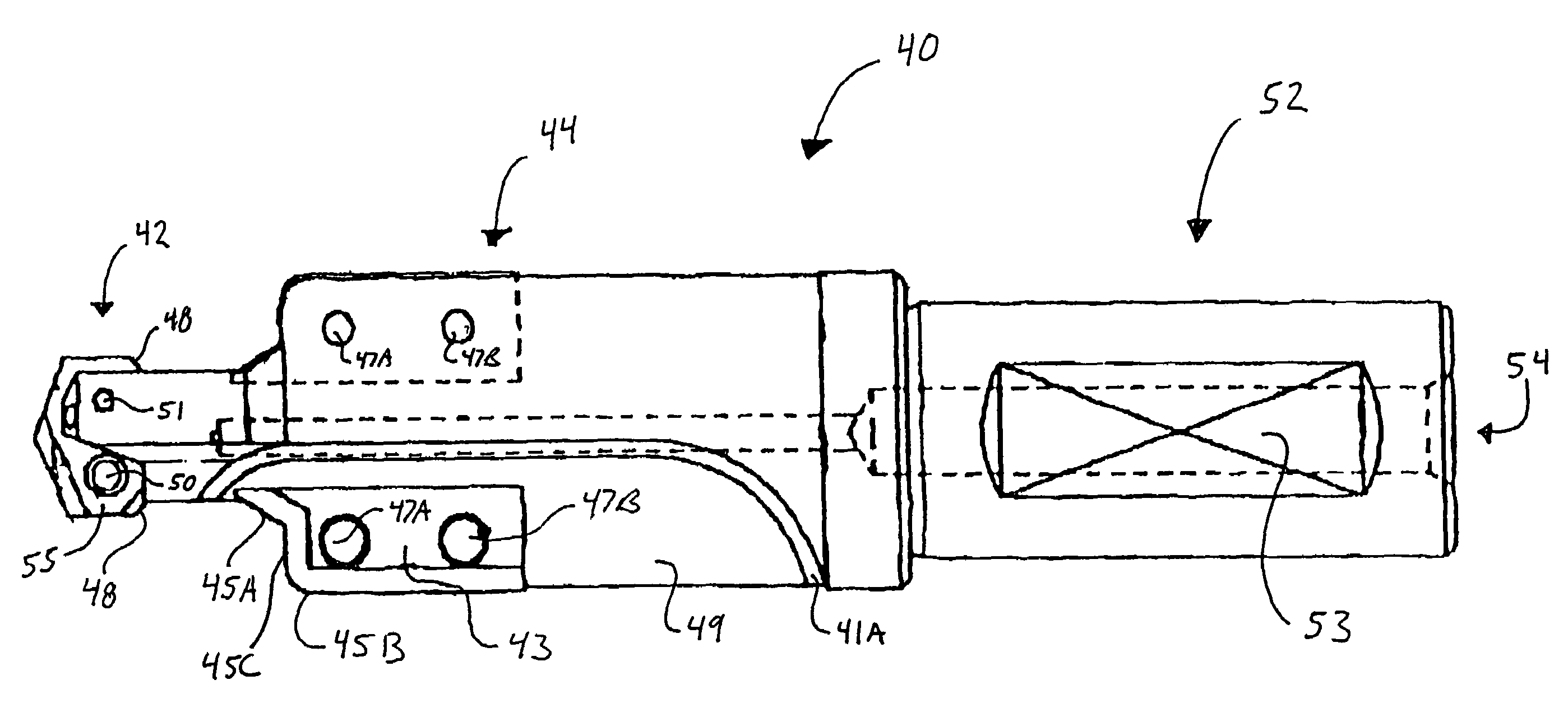
[0023]Referring again to the drawings, there is illustrated generally at 40 in FIG. 3, a single tool for forming a lug hole through a vehicle wheel disc hub that is in accordance with the invention. An enlarged end view of the cutting end of the tool 40 is shown in FIG. 4A and an enlargement of a side view of the cutting end of the tool 40 is shown in FIG. 4B. In the preferred embodiment, the tool 40 is formed from carbide. As best seen in FIG. 4B, the tool 40 includes an end portion 42 having a reduced diameter that extends axially from a mid-portion 44. The end portion 42 carries a removable spade drill bit 55. A slot 49 formed in the end portion 42 receives the spade drill bit 55.

[0024]Additionally, two notches 56 are formed in opposite sides of the tool end portion 42 to allow the spade drill bit 55 to be fastened to the end portion 42 by a pair of threaded fasteners, preferably by TORX® screws, 50 and 51. The use of threaded fasteners allows for easy replacement of a damaged sp...


PUM

PropertyMeasurementUnit
angleaaaaaaaaaa
diameteraaaaaaaaaa
widthaaaaaaaaaa

Abstract

A single tool that provides multiple machining operations for forming a lug hole through a vehicle wheel hub includes an end portion having a first diameter and a mid-portion having a second diameter that is greater than the first diameter. A spade drill bit is mounted upon the end portion and a bore cutting tool is mounted upon the mid-portion.

Description

BACKGROUND OF INVENTION[0001]This invention relates in general to the manufacture of vehicle wheels and in particular to a tool and method for forming lug holes through a vehicle wheel hub.[0002]Vehicle wheels include an annular wheel rim that supports a pneumatic tire. A wheel disc typically extends across the outboard end of the wheel rim and is formed having a pleasing esthetic shape. The wheel disc usually includes a central wheel hub supported within the wheel rim by a plurality of radial spokes. Apertures formed through the wheel hub allow attachment to a vehicle axle.[0003]Light weight vehicle wheels cast from alloys of aluminum, magnesium, and titanium have become increasingly popular. Such wheels may be cast as one piece and then finished with a number of machining operations or assembled from several components that also are machined to final dimensions. Regardless of the method used, the manufacture of vehicle wheels is highly automated.[0004]One of the steps that are req...

Claims


Application Information

Patent Timeline
Patent Type & Authority Patents(United States)
IPC IPC(8): B23B51/02B23B51/08B23B35/00B23B51/00B23B51/10B23P13/02B60B3/16
CPCB23B51/08B23B51/10B23P13/02B23B51/0009B23B2270/56Y10T408/03Y10T408/352Y10T408/34Y10T408/356Y10T408/906Y10S408/713B23B51/00035
Inventor GATTON, GEOFFREY L.SEILER, DAVE
Owner HAYES LEMMERZ INT
Why Eureka
Try Eureka