

Bionest reactor for the application of anaerobic wastewater treatment and bioenergy recovery
a bionest reactor and bioenergy recovery technology, applied in the nature of treatment water, multi-stage water/sewage treatment, separation process, etc., can solve the problems of difficult formation of granules during uasb, poor uasb treatment methods of lipid-rich wastewater, and limited granule blanket reactors. achieve uniform hydraulic retention tim
- Summary
- Abstract
- Description
- Claims
- Application Information
AI Technical Summary
Benefits of technology
Problems solved by technology
Method used
Image

Examples
example 1
Analysis of an Existing, Non-bionest Wastewater Treatment: Dairy Wastewater from a Hawaiian Cattle Farm
[0117]The system parameters of an existing, nonbionest wastewater treatment facility operated in Oahu, Hawaii were measured for comparative purposes. The source of the wastewater was a 1600 head livestock farm, including 1,000 milk cows and a milk-producing facility.
[0118]Wastewater flow: 300,000 gallon / day (1,136 m3 / day).
[0119]Total COD Concentration: 4000–6500 mg / L.
[0120]Soluble COD: 1200–2000 mg / L.
[0121]The discharged wastewater flowed into two receiving lagoons, each with the following dimensions: 50×250×6 ft3 (15.24×76.2×1.83 m3). The effluent was discharged to 10 acres of land planted with California Grass.
[0122]The source and characteristics of the dairy wastewater generated from the diary farm are indicated below in Table 4. The various types of wastewater present in the dairy farm were analyzed to determine TCOD, SCOD, N, P, TSS, and VSS. Total COD, soluble COD, total susp...
example 2
Reactor Set Up and Startup
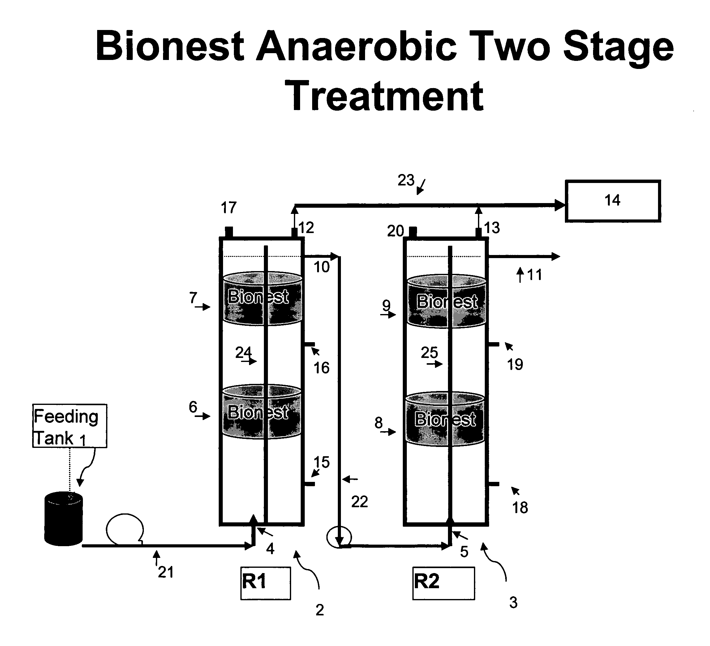
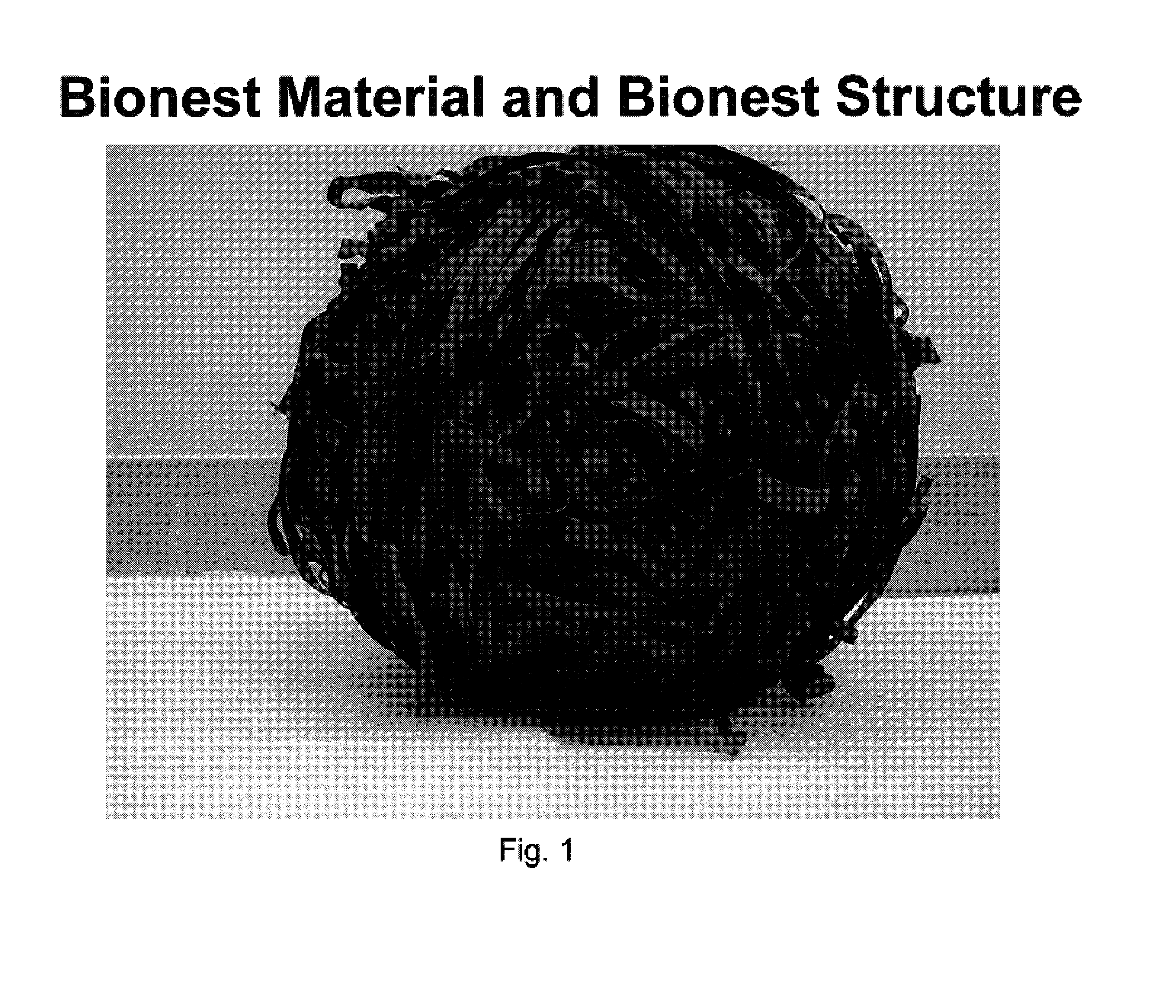
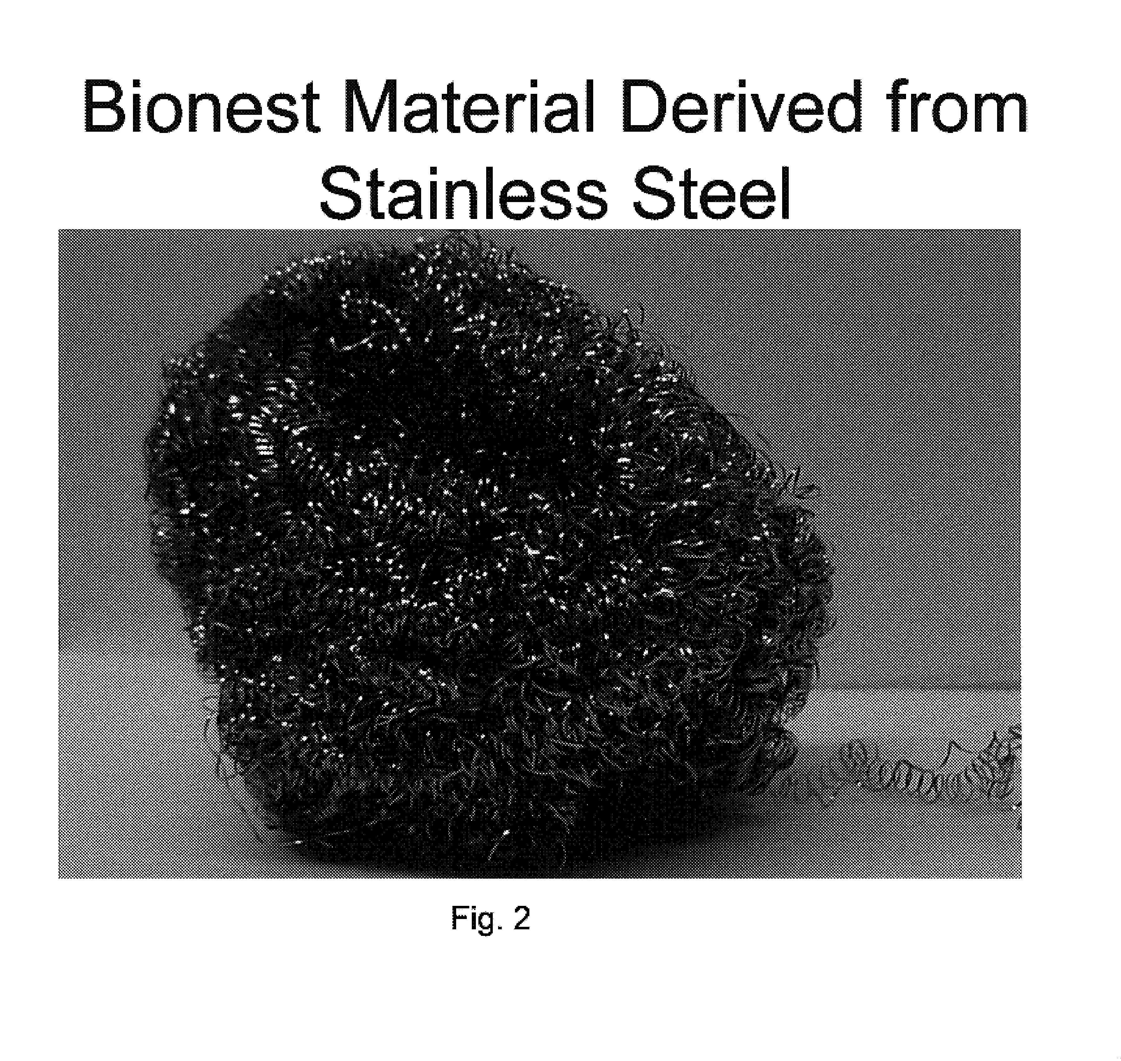
[0125]The apparatus was set up according to FIG. 3. A two-stage bioreactor (10 liter each) as shown in FIG. 5, was designed and filled with two bionest bioreactors connected in series by tubing. Each individual bioreactor contained two bionest units. They were filled with two layers of medium resulting in 98% void volume in the reactor. The reactor was made of transparent PVC in order to be able to observe the sludge formation and accumulations. Three sample outlets were designed to test the sludge distribution at the different heights of 15 cm, 65 cm and 90 cm, respectively. A special puncture needle was designed to take samples from the bionest. Table 5 shows the main parameters of the two-stage bionest reactors and bionest content. FIG. 1 shows an example of the bionest structure, FIG. 3 shows a diagram of the two-stage anaerobic bioreactor, and FIG. 4 shows a diagram of the two-stage anaerobic reactor plus an aerobic bioreactor. FIG. 5 is a photograph o...
example 3
Operating the Bionest Bioreactor
[0129]The bionest system was set up as in Example 2, above. Milk parlor wastewater was collected and stored in a refrigerator (about 4° C.) prior to use. This chilling was for convenience and reproducibility of starting material. In operation there is no need to pre-chill the wastewater. The stored wastewater was fed into reactor directly from the refrigerator. Seeded sludge was collected from an existing anaerobic reactor operated by batch. In order to test the sludge distribution in the bionest bioreactor, and to compare the effects of various operation schedules, sludge from the bioreactor was sampled both at the start of the feeding period and at the end of the feeding period. Sludge sampling was collected from the sampling outlets of various heights. The sludge samples were removed from the bionest bioreactor using a long puncture needle connected with a vacuum ball. A single stage reactor having the same sludge content as in the bionest bioreact...
PUM
| Property | Measurement | Unit |
|---|---|---|
| thickness | aaaaa | aaaaa |
| thickness | aaaaa | aaaaa |
| hydraulic retention time | aaaaa | aaaaa |
Abstract
Description
Claims
Application Information