Display device for working machine
- Summary
- Abstract
- Description
- Claims
- Application Information
AI Technical Summary
Benefits of technology
Problems solved by technology
Method used
Image
Examples
first embodiment
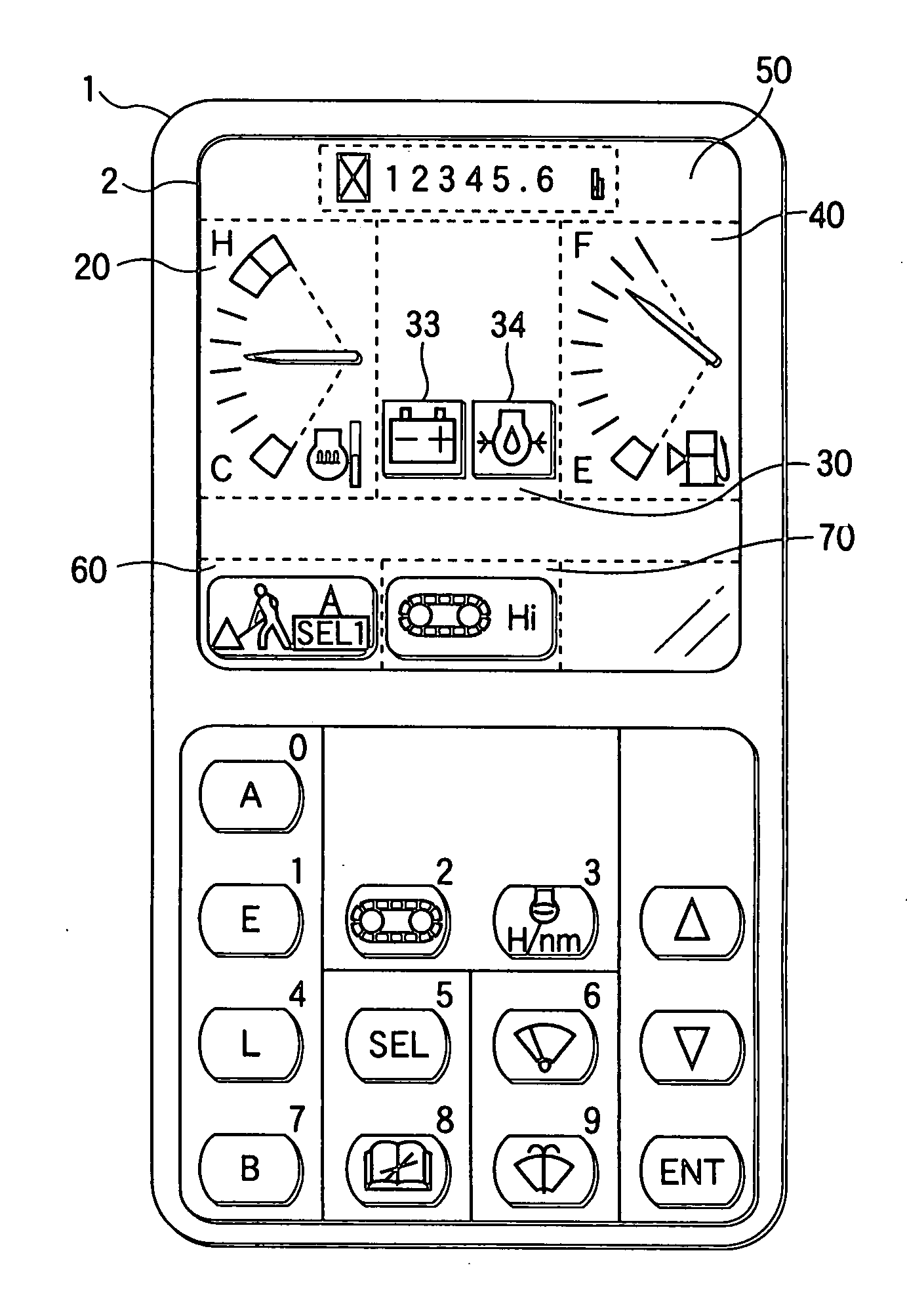
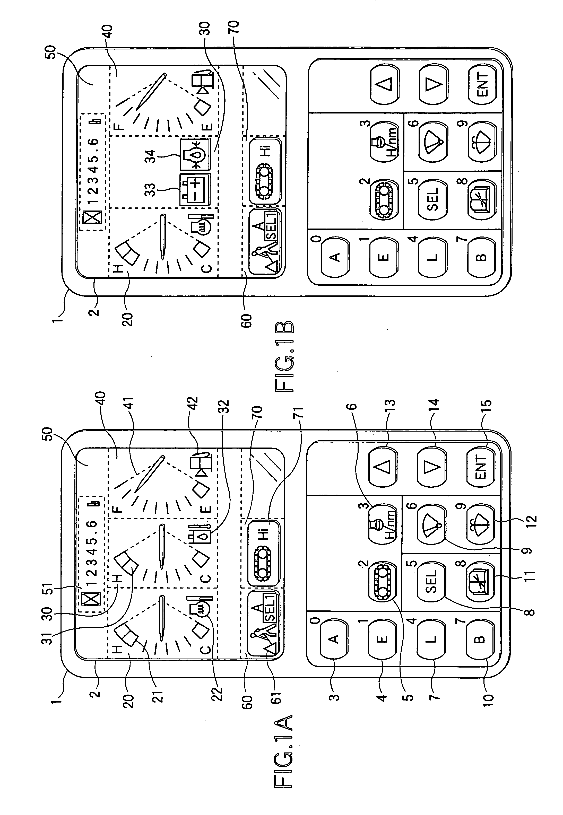
[0105]A display device for a working machine according to the invention will be described on a monitor panel to be used in a hydraulic shovel with reference to the accompanying drawings.
[0106]Here in this embodiment, the state change indication mark to be displayed on the display screen is preferably exemplified by a caution mark to be displayed where an abnormality occurs.
[0107]The hydraulic shovel is provided with a running equipment including a running control lever, a running hydraulic motor and a crawler. When the running control lever is controlled, more specifically, the running hydraulic motor is activated according to the control of the running control lever so that the crawler connected to the running hydraulic motor is driven according to the activation of the running hydraulic motor. On the other hand, the hydraulic shovel is provided with a working equipment including a working machine control lever, a working machine hydraulic cylinder and a working machine (e.g., a b...
second embodiment
[0160]Next, a second embodiment will be described with reference to FIGS. 9A and 9B.
[0161]In the second embodiment, the display device of the working machine according to the invention will be described on a monitor panel which is employed in an arm crane having a hook attached to the bucket portion of the hydraulic shovel, with reference to the accompanying drawings.
[0162]FIG. 9A is a view showing the display screen before switches are depressed, and FIG. 9B is a view showing the display screen after the switches were depressed.
[0163]Here, the screen construction of the display screen 2 shown in FIGS. 1A and 1B to FIG. 7 is different from that of the display screen 2 shown in FIGS. 9A and 9B. Of the individual state indication marks shown in FIGS. 9A and 9B, the same state indication marks as those shown in FIGS. 1A and 1B to FIG. 7 will be described by designating them by the common reference numerals.
[0164]On the display screen 2, there are displayed the state indication marks 21...
third embodiment
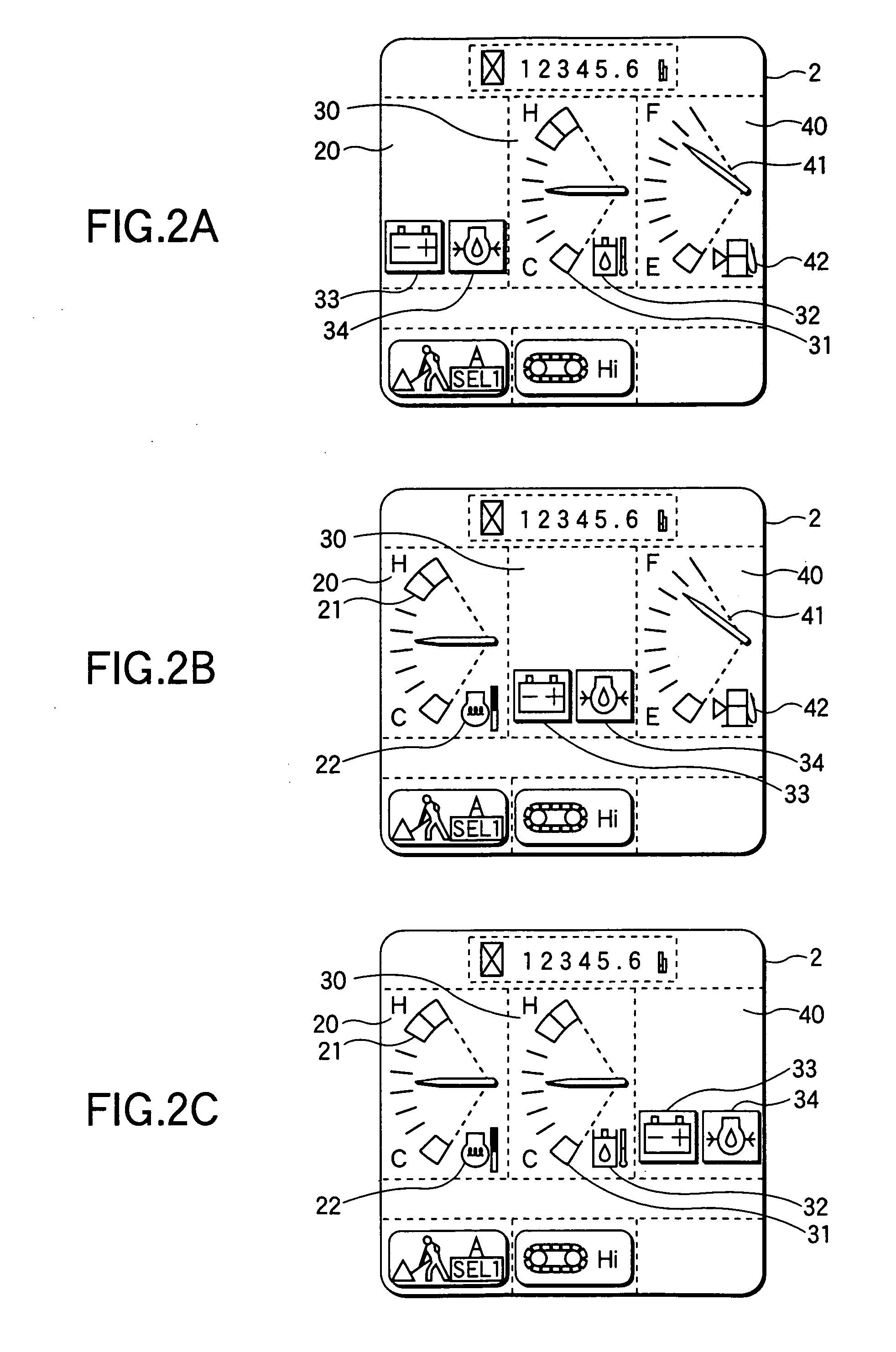
[0181]Next, a third embodiment will be described with reference to FIGS. 10A and 10B and FIGS. 11A and 11B.
[0182]FIG. 10A is a view showing the display screen before a predetermined abnormality occurs, and FIG. 10B is a view showing the display screen after the predetermined abnormality occurred.
[0183]If the battery voltage drops where the display screen 2 is in the state shown in FIG. 10A, there are reduced and displayed the working oil temperature indication mark 31 and the working oil temperature caution mark 32 which have been displayed in the display segment 92. Moreover, the battery caution mark 33 is displayed in that portion of the display segment 92, in which the working oil temperature indication mark 31 is reduced.
[0184]FIG. 11A is a view showing the display screen before a predetermined abnormality occurs, and FIG. 11B is a view showing the display screen after the predetermined abnormality occurred.
[0185]If the battery voltage drops where the display screen 2 is in the ...
PUM
 Abstract
Description
Claims
Application Information
 - R&D
- Intellectual Property
- Life Sciences
- Materials
- Tech Scout
- Unparalleled Data Quality
- Higher Quality Content
- 60% Fewer Hallucinations
Browse by: Latest US Patents, China's latest patents, Technical Efficacy Thesaurus, Application Domain, Technology Topic, Popular Technical Reports.
© 2025 PatSnap. All rights reserved.Legal|Privacy policy|Modern Slavery Act Transparency Statement|Sitemap|About US| Contact US: help@patsnap.com


