Method for manufacturing a permanent-magnet excited rotor for a high speed electric motor

a high-speed electric motor and excited rotor technology, which is applied in the direction of magnetic circuit rotating parts, magnetic circuit shapes/forms/construction, magnetic bodies, etc., can solve the problems of redistribution of mass in the rotor and severely affect the rotor balancing, and achieves fast and simple manufacturing, improved balancing effect, and improved balancing

Inactive Publication Date: 2007-06-12
ATLAS COPCO AIRPOWER NV
View PDF17 Cites 27 Cited by
  • Summary
  • Abstract
  • Description
  • Claims
  • Application Information

AI Technical Summary

Benefits of technology

[0014]The aim of the invention is to avoid the above mentioned drawbacks and to provide a method for manufacturing a permanent-magnet excited rotor which does not show the above-mentioned drawbacks and

Problems solved by technology

The magnets must also be mounted on the rotor in a way so they do not move when the sleeve is mounted, otherwise they may move when rotating, causing a redistribution of mass in the ro

Method used


Image

  • Method for manufacturing a permanent-magnet excited rotor for a high speed electric motor
  • Method for manufacturing a permanent-magnet excited rotor for a high speed electric motor
  • Method for manufacturing a permanent-magnet excited rotor for a high speed electric motor

Examples


Embodiment Construction

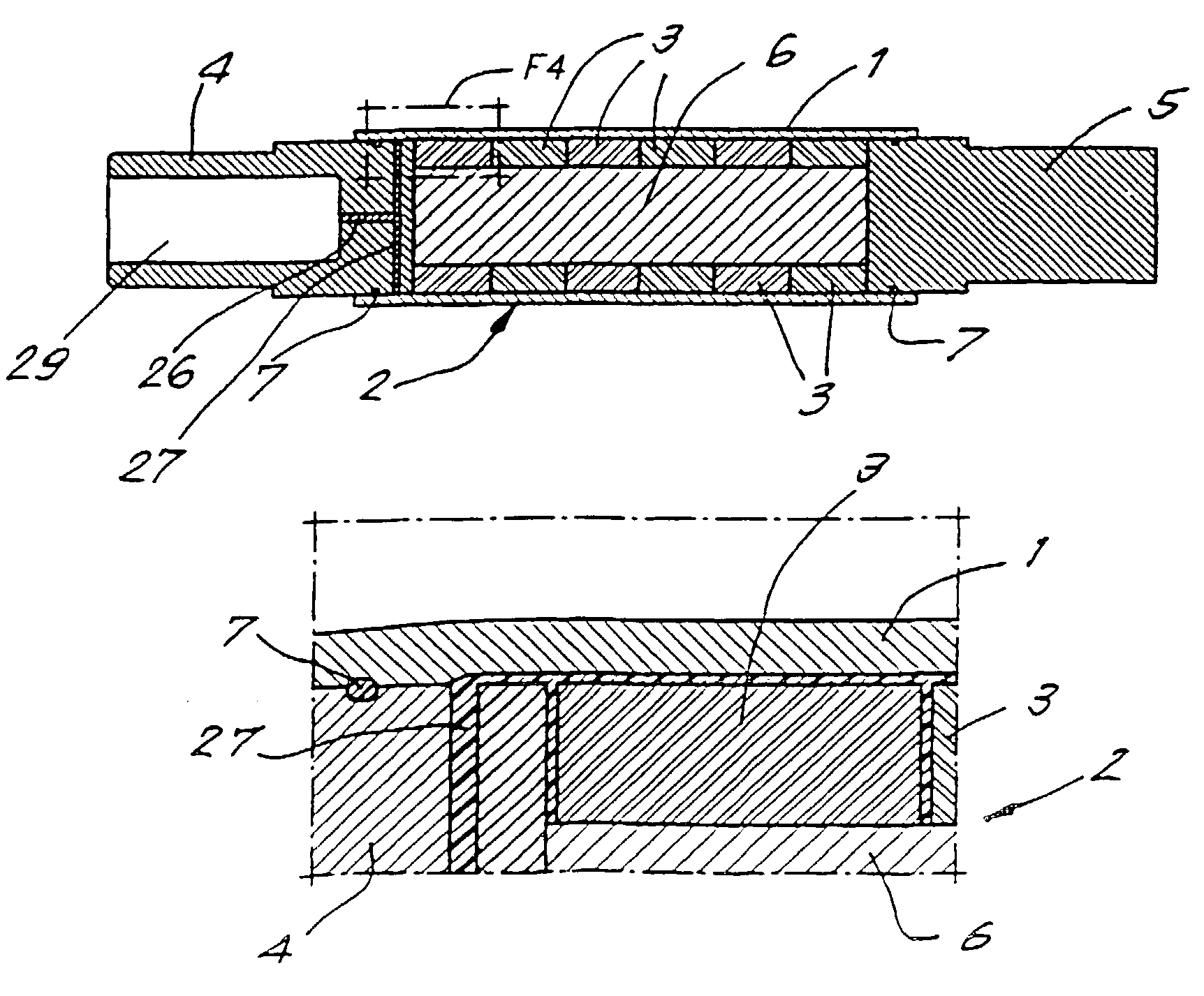
[0026]A permanent magnet excited rotor for a high speed electric motor is manufactured by mounting a support sleeve 1 with a pre-tension around the rotor body 2 containing permanent magnets 3.

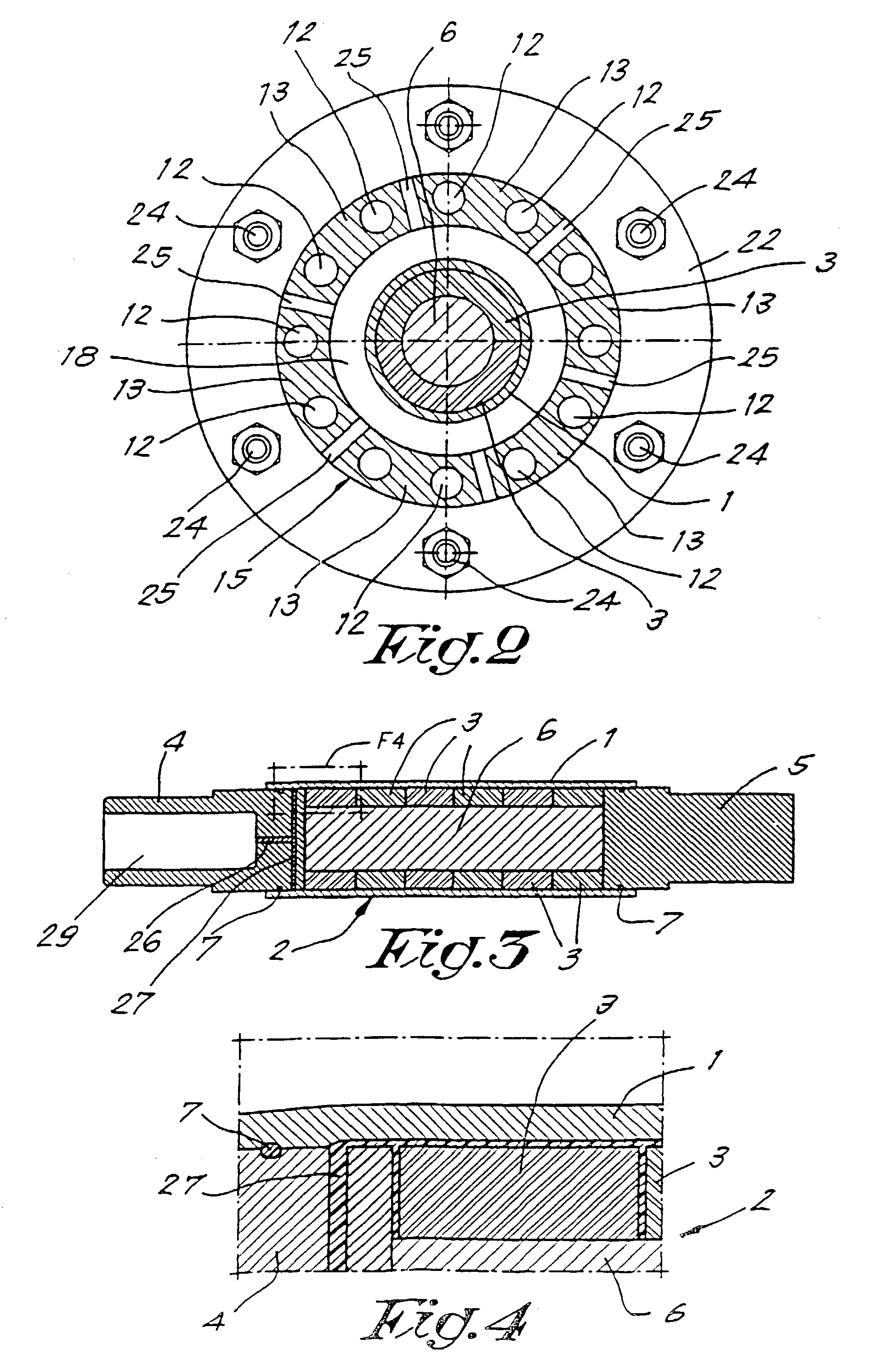
[0027]As shown in the FIGS. 1 to 4, the rotor body 2 is made from a skeleton composed of two end pieces 4 and 5 and a shaft 6 connecting both end pieces, the shaft being surrounded by the magnets 3.

[0028]O-ring seals 7 are mounted on the end-pieces 4 and 5.

[0029]Rings of permanent magnets 3, shaped as two half circle ring segments for a two pole motor or four quarter circle segments for a four pole motor, are placed around the shaft 6.

[0030]The sleeve 1, made from carbon fibres, is slid on to the rotor body 2.

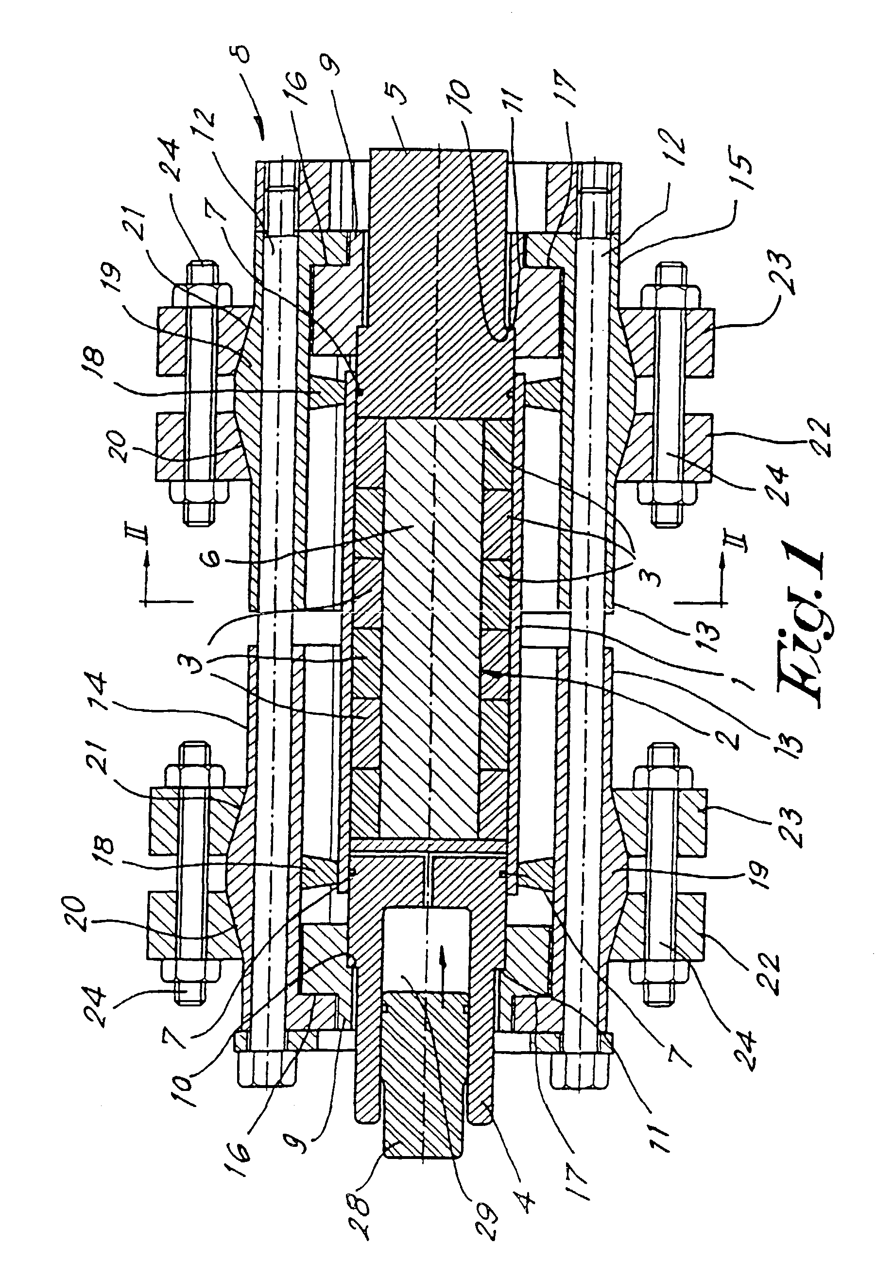
[0031]The rotor body 2, surrounded by the sleeve 1, is now clamped in a clamping and injecting device 8 as shown in FIG. 1.

[0032]The rotor body 2 is clamped axially via end rings 9 presenting a shoulder 10 abutting a corresponding outwardly projecting shoulder 11 of the end pieces 4 and 5....


PUM

PropertyMeasurementUnit
Temperatureaaaaaaaaaa
Pressureaaaaaaaaaa
Melting pointaaaaaaaaaa

Abstract

The invention relates to a method for manufacturing a permanent-magnet excited rotor for a high speed electric motor, according to which method a support sleeve (1) is mounted with a pre-tension around the rotor body (2), characterised in that the sleeve is expanded by a liquid that solidifies and is solid at the working temperatures of the rotor, said liquid is injected under pressure between the sleeve and the rotor body and held under pressure during solidification.

Description

BACKGROUND OF THE INVENTION[0001]1. Field of the Invention[0002]This invention relates to a method for manufacturing a permanent-magnet excited rotor for a high speed electric motor, according to which method a support sleeve is mounted with a pre-tension around the rotor body.[0003]“High speed” motor means here each motor having a maximum speed requiring a support sleeve to keep the rotor from breaking, more particularly to keep the magnets, which have very low tensile strength, from breaking.[0004]In practice magnets can mostly resist forces of 50 to 70 kPa, while in high speed motors tensile forces higher than 100 kPa can exist at maximum speed.[0005]For high speed permanent-magnet rotors, a support sleeve is also required to keep the magnets securely attached to the rotor body and maintain these magnets under compression under all operating speeds and temperatures of the rotor.[0006]To accomplish this, the support sleeve must be mounted on the rotor with a specified minimum inte...

Claims


Application Information

Patent Timeline
IPC IPC(8): H02K15/02H02K1/27H02K15/03
CPCH02K1/2726H02K1/2733H02K15/03Y10T29/53143Y10T29/49009Y10T29/49012Y10T29/49075
Inventor NILSON, THORD AGNE GUSTAF
Owner ATLAS COPCO AIRPOWER NV
Why Eureka
Try Eureka