Defrost mode for HVAC heat pump systems

a heat pump and defrost mode technology, applied in the direction of defrosting, domestic cooling apparatus, etc., can solve the problems of unduly high temperature of refrigerant leaving the evaporator, problems elsewhere in the system, etc., to prolong the life of the circuit components, avoid the effect of smoother transition and abrupt pressure variation

Inactive Publication Date: 2007-06-12
CARRIER CORP
View PDF21 Cites 13 Cited by
  • Summary
  • Abstract
  • Description
  • Claims
  • Application Information

AI Technical Summary

Benefits of technology

[0008]Moreover, protection for the water remaining in the heat exchanger during a defrost mode is also disclosed. The protection may take the form of periodically operating the water pump during defrost mode to remove the water in the heat exchanger such that it is not subject to the high refrigerant heat for an undue length of time. Alternatively, the water pump may not be stopped until the refrigerant temperature is lowered to a point such that the water would tend not to boil. That is, some method for beginning to lower the refrigerant temperature at the compressor outlet can be initiated such that before the water pump is stopped, the refrigerant temperature has lowered below the boiling point of water. In a preferred embodiment, the regulation of the refrigerant temperature is done with a dual (or nested) control loop. A first control loop compares the actual temperature to a target temperature, and determines a new refrigerant discharge pressure for the compressor based upon the difference between the target and actual refrigerant temperature. The second portion of the control loop achieves that new target pressure by controlling the expansion device. The use of the dual control loop provides a smoother transition than a single direct control loop would provide. Abrupt pressure variation is avoided, which will extend the life of the circuit components. Further, this control loop will allow the discharge temperature to be maintained accurately near the target value, which will minimize the defrost time.

Problems solved by technology

Moreover, as the water begins to melt, if the temperature is not lowered, such as by air, the temperature of the refrigerant leaving the evaporator can begin to reach unduly high temperatures.
This could result in problems elsewhere within the system.

Method used


Image

  • Defrost mode for HVAC heat pump systems
  • Defrost mode for HVAC heat pump systems

Examples


Embodiment Construction

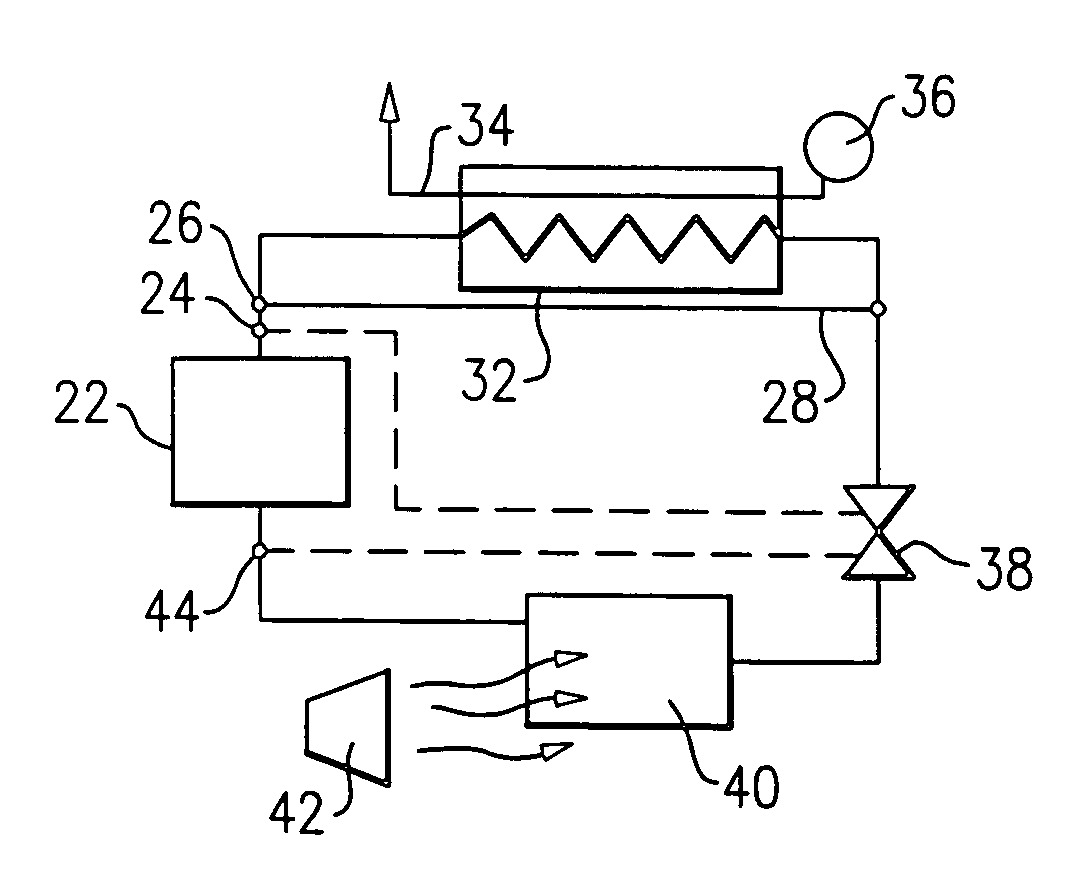
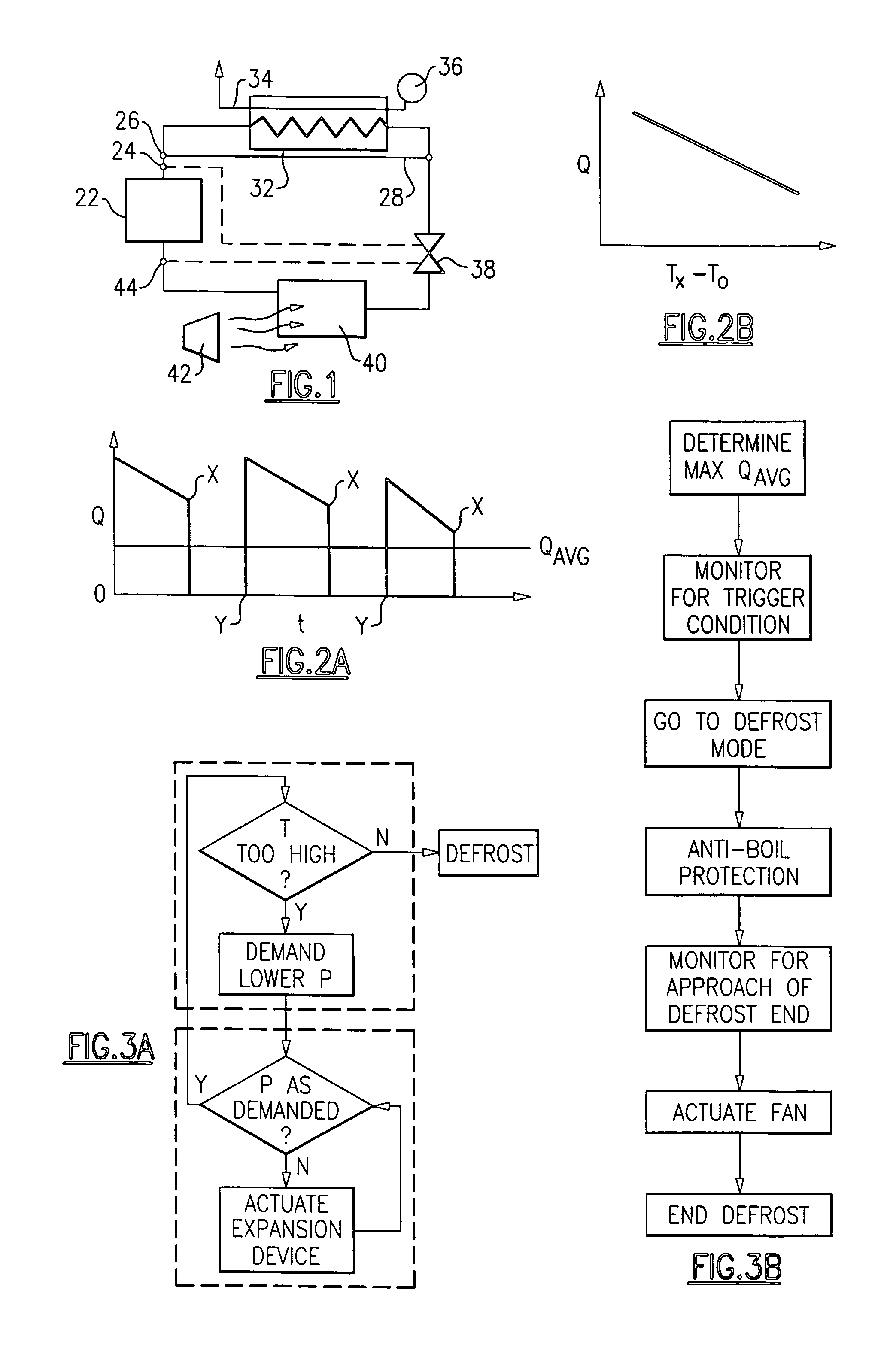
[0017]A heat pump cycle 20 is illustrated schematically in FIG. 1. As known, a compressor 22 compresses a refrigerant and discharges the refrigerant downstream toward heat exchanger 32. As shown, a sensor 24 is positioned on this downstream line. Further, a valve 26 selectively allows the flow into a bypass line 28, which will bypass a portion of the refrigerant to a downstream point 30, bypassing the heat exchanger 32. Bypass line 28 is optional, and is a component to provide a defrost function as will be explained below. A hot water line 34 passes in heat exchange relationship with the refrigerant in the heat exchanger 32. A hot water pump 36 drives the flow of the water through the heat exchanger 32.

[0018]An expansion device 38 is positioned downstream of the heat exchanger 32, and an evaporator 40 is downstream of the expansion device 38. Typically, the evaporator 40 includes heat transfer coils. A fan 42 blows air over the evaporator 40 to heat the refrigerant in the evaporator...


PUM


Abstract

A heat pump, and in particular a heat pump for heating a hot water supply is provided with an improved defrost mode. The defrost mode is actuated to remove frost from an outdoor evaporator that may accumulate during cold weather operation. An algorithm for operation of the defrost mode is developed experimentally by seeking to maximize the heat transfer provided by the refrigerant. A heating system condition is experimentally related to the heat transfer capacity. One then maximizes the average heat transfer capacity to determine the optimum initiation point for the defrost mode. Further, protections are included into the defrost mode. When the heat pump is utilized to heat hot water, methods are provided to prevent the water that remains in the heat exchanger from becoming unduly heated. In one method, the water pump may be periodically operated to move the water. In a second method, a control ensures the discharge pressure of the refrigerant leaving the compressor is reduced, and that the water pump is not stopped until that reduced temperature falls below a predetermined maximum. The temperature reduction is achieved through a dual control loop wherein a temperature that is too high results in a new desired discharge pressure. The control achieves the new desired pressure by controlling the expansion device. In another protection feature, as a control determines that the defrost mode is nearing its end, an evaporator fan is run to remove melted water from the evaporator coils, and also to ensure the refrigerant leaving the evaporator does not reach unduly high pressure or temperatures.

Description

BACKGROUND OF THE INVENTION[0001]This invention relates to several improvements for determining when to initiate a defrost mode for a heat pump, and also to protect associated systems such as a hot water supply system during a defrost mode.[0002]Heating, ventilation and air conditioning (HVAC) systems are utilized to provide cooling and heating in buildings. Typically, a compressor delivers a refrigerant to a heat exchanger which is a heat exchanger associated with the interior of a building. The refrigerant passes to an expansion device downstream of the heat exchanger, and downstream of the expansion device to an evaporator. The evaporator is typically a heat exchanger that exchanges heat with an outside environment.[0003]When an HVAC system is utilized to provide heating, it can be said to be in a heat pump mode. Under such conditions, the evaporator may be in a very cold environment, such as during winter. Problems can arise in that frost can form on the evaporator heat exchange...

Claims


Application Information

Patent Timeline
Patent Type & Authority Patents(United States)
IPC IPC(8): F25D21/06F25B30/02F25B39/04F25B47/02F25D21/00
CPCF25B30/02F25B47/022F25B2339/047F25B2400/0403F25B2500/18F25B2500/19F25B2700/133F25B2700/2106F25B2700/21151
Inventor CONCHA, JULIOCHEN, YUPARK, YOUNG KYUSIENEL, TOBIAS H.
Owner CARRIER CORP
Why Eureka
Try Eureka