Motor vehicle sway control assembly

a technology for motor vehicles and assembly parts, applied in vehicle components, resilient suspensions, interconnection systems, etc., can solve the problems of affecting the ability of close tolerance control, the life expectancy of use, the manufacturing cost, etc., and achieves the effect of reducing driver fatigue, long lasting, and easy maintenan

Inactive Publication Date: 2007-06-12
ROGERS ROBERT LOUIS
View PDF27 Cites 15 Cited by
  • Summary
  • Abstract
  • Description
  • Claims
  • Application Information

AI Technical Summary

Benefits of technology

[0014](f) to reduce driver fatigue caused by the continuous driver steering corrections imposed by the continuous side to side swaying allowed by some rear suspension systems.
[0015]Further advantages are to provide a design that is lightweight, strong, easily maintainable and long lasting. All primary moving parts have rubber seals to protect from dirt ingestion. They also have grease nipples to allow continued maintenance. Examples are the rod end attachments and the telescoping rod assembly. The ball rod ends used are commercially available heavy-duty truck front wheel steering tierod ends. They are readily available at many automotive parts stores, thus allowing easy replacement of the parts that may experience wear during use. This design also assures minimal unwanted side movement as would be allowed by polyurethane or rubber being used in the construction of the rod end bearings as provided in some prior art designs currently available on the market.

Problems solved by technology

Any rod end bearing design, polyurethane, rubber, greaseable, not greaseable, sealed or unsealed will only affect the assembly's close tolerance control abilities, its manufacturing cost and its in use life expectancy.

Method used


Image

  • Motor vehicle sway control assembly
  • Motor vehicle sway control assembly
  • Motor vehicle sway control assembly

Examples


Embodiment Construction

—FIGS. 1,2,3, 4, and 5—PREFERRED EMBODIMENT

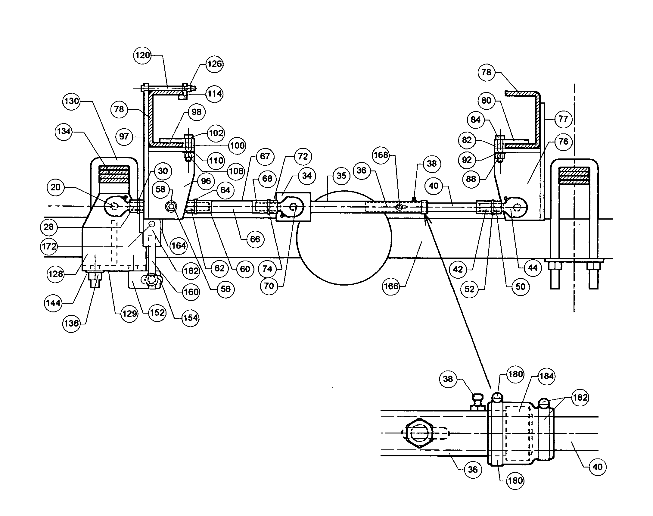
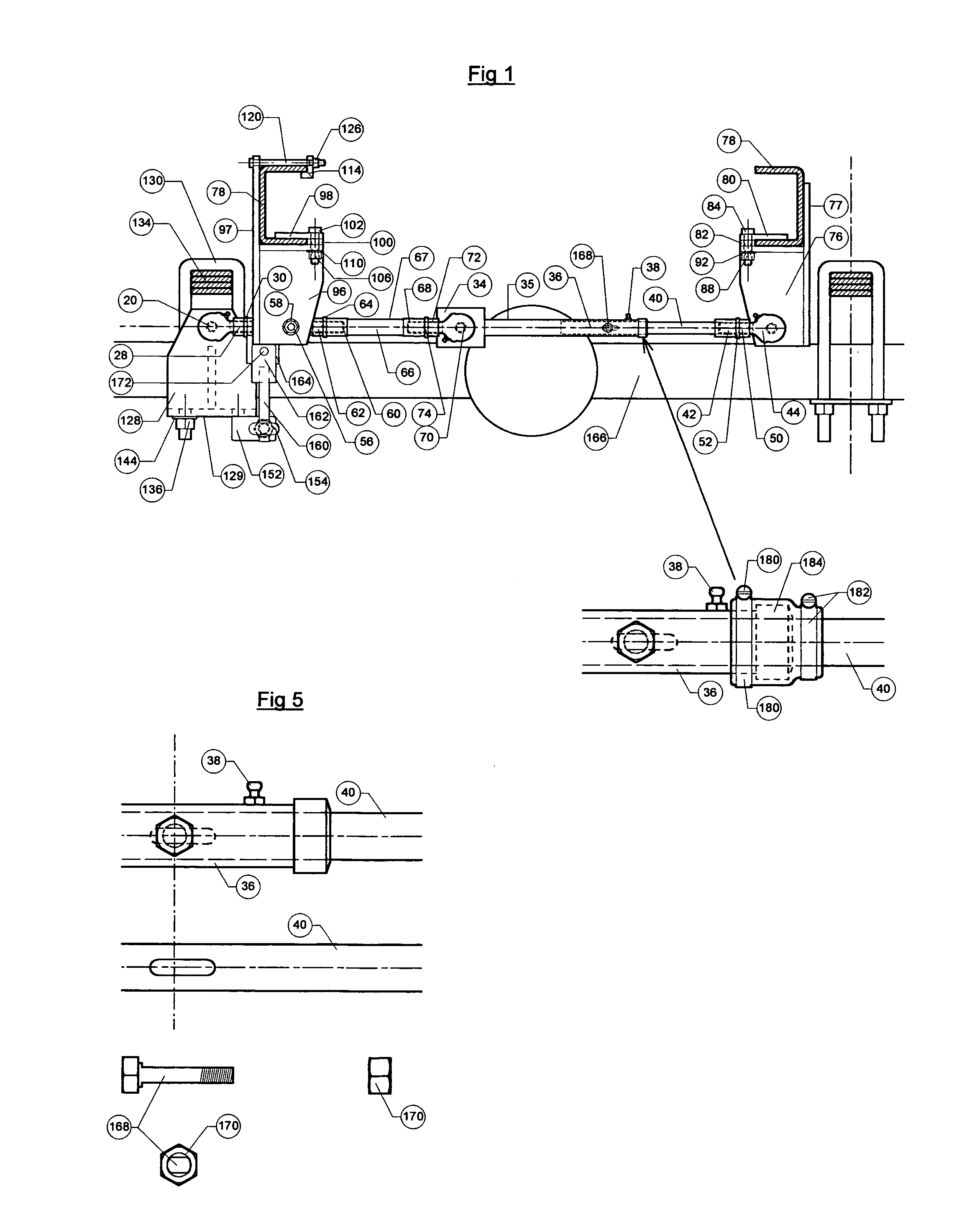
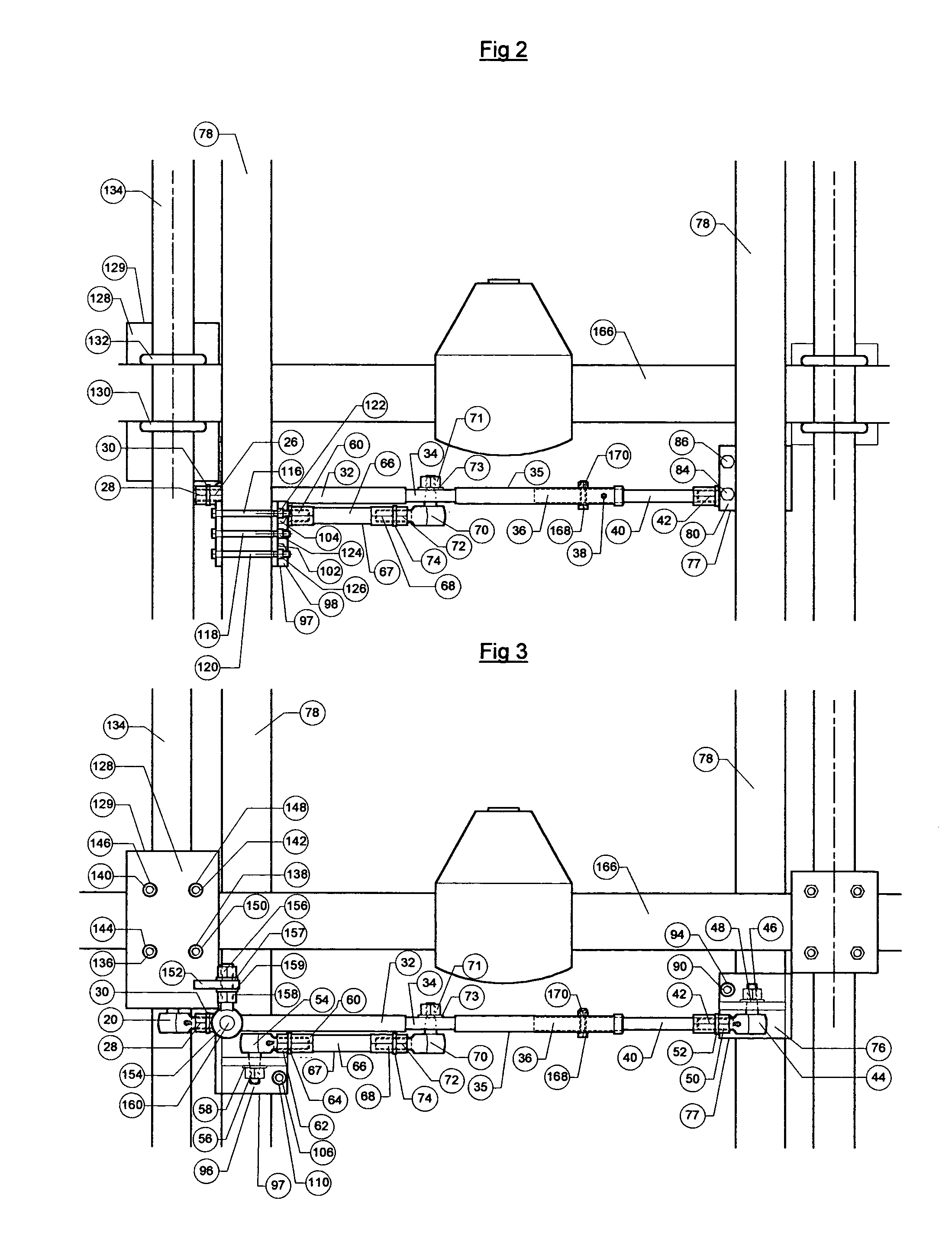
[0027]A preferred embodiment of the sway bar invention is illustrated in FIGS. 1, 2, 34 and 5. The sway control rod assembly 35 is a welded, machined and bolted assembly. It is manufactured from steel pipe stock, steel plate stock, inside diameter threaded steel hexagon bar stock, steel rod stock, rod end bearing assemblies, nuts, and locking washers. Starting at the left side of the assembly and going right the detail parts include a rod end bearing 20, attachment nut 22 (not shown), and locking washer 24 (not shown). Rod end bearing 20, its attachment nut 22 (not shown) and locking washer 24 (not shown) are threaded into hexagon rod end attachment 26 and locked in position by locking nut 28 and locking washer 30. Hexagon rod end attachment 26 is welded to left sway control rod 32. A mounting plate 34 is welded to left sway control rod 32. Mounting plate 34 has a machined hole in its center position. The hole is machined to accept the tier...


PUM


Abstract

An improved vehicle sway control assembly designed to limit excessive side swaying of front engine rear axle driven motor vehicles during all driving conditions. The system utilizes two frame brackets (77), (97), one axle/spring bracket (129), and two rods (35), (67). The first rod (35) has one end attached to a frame bracket (77) and the other end to the axle/spring bracket (129). It incorporates a telescoping feature allowing the rod end nearest the frame bracket (77) to telescope. The second rod (67) is attached on the opposite side to a frame bracket (97) on one end and a mid section plate (34) on the telescoping rod (35) on the other end. The counter rotational arch of the second rod (67) will force the telescoping rod (35) to extend thus canceling the telescoping rod (35) arch curve travel if it were a solid rod. The overall design will limit axle (166) to frame (78) side movement while providing near straight vertical axle (166) travel.

Description

CROSS-REFERENCE TO RELATED APPLICATION[0001]Not ApplicableFEDERALLY SPONSORED RESEARCH[0002]Not ApplicableSEQUENCE LISTING OR PROGRAM[0003]Not ApplicableBACKGROUND OF THE INVENTION—FIELD OF INVENTION[0004]This invention pertains to a sway control device that will, when installed, greatly reduce unwanted vehicle side to side swaying created by wind, uneven road surfaces or other passing vehicles when the vehicle is traveling on smooth or bumpy surfaces.BACKGROUND OF THE INVENTION[0005]Currently most factory produced front engine powered rear axle driven vehicles have their rear axle assembly mounted on coil springs, leaf springs or air suspension assemblies with roll bars and shock absorbers. These vehicles rely on the rigidity of these parts to eliminate unwanted side to side swaying of the vehicle due to the wind, uneven road surfaces or passing vehicles. In many cases the overall allowable dimensional clearances between the suspension parts along with the flexing of the spring ass...

Claims


Application Information

Patent Timeline
Patent Type & Authority Patents(United States)
IPC IPC(8): B60G21/05
CPCB60G9/003B60G2200/31B60G2200/3415
Inventor ROGERS, ROBERT LOUIS
Owner ROGERS ROBERT LOUIS
Why Eureka
Try Eureka