
Brushless synchronous motor

a synchronous motor and brushless technology, applied in the direction of motor/generator/converter stopper, dynamo-electric converter control, magnetic circuit shape/form/construction, etc., can solve the problem of effectively limited dimensional variation, and achieve the effect of increasing the output power of the motor and small air gap

Active Publication Date: 2007-06-12
DENSO CORP
View PDF16 Cites 15 Cited by
  • Summary
  • Abstract
  • Description
  • Claims
  • Application Information

AI Technical Summary

Benefits of technology

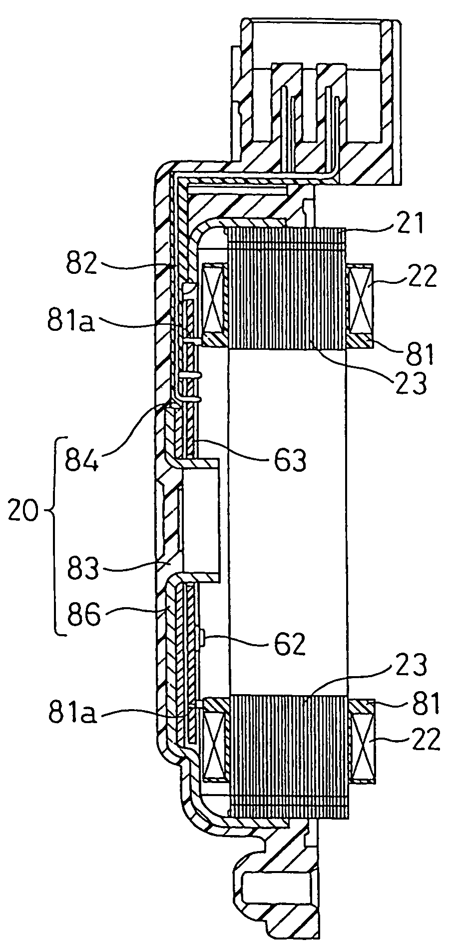
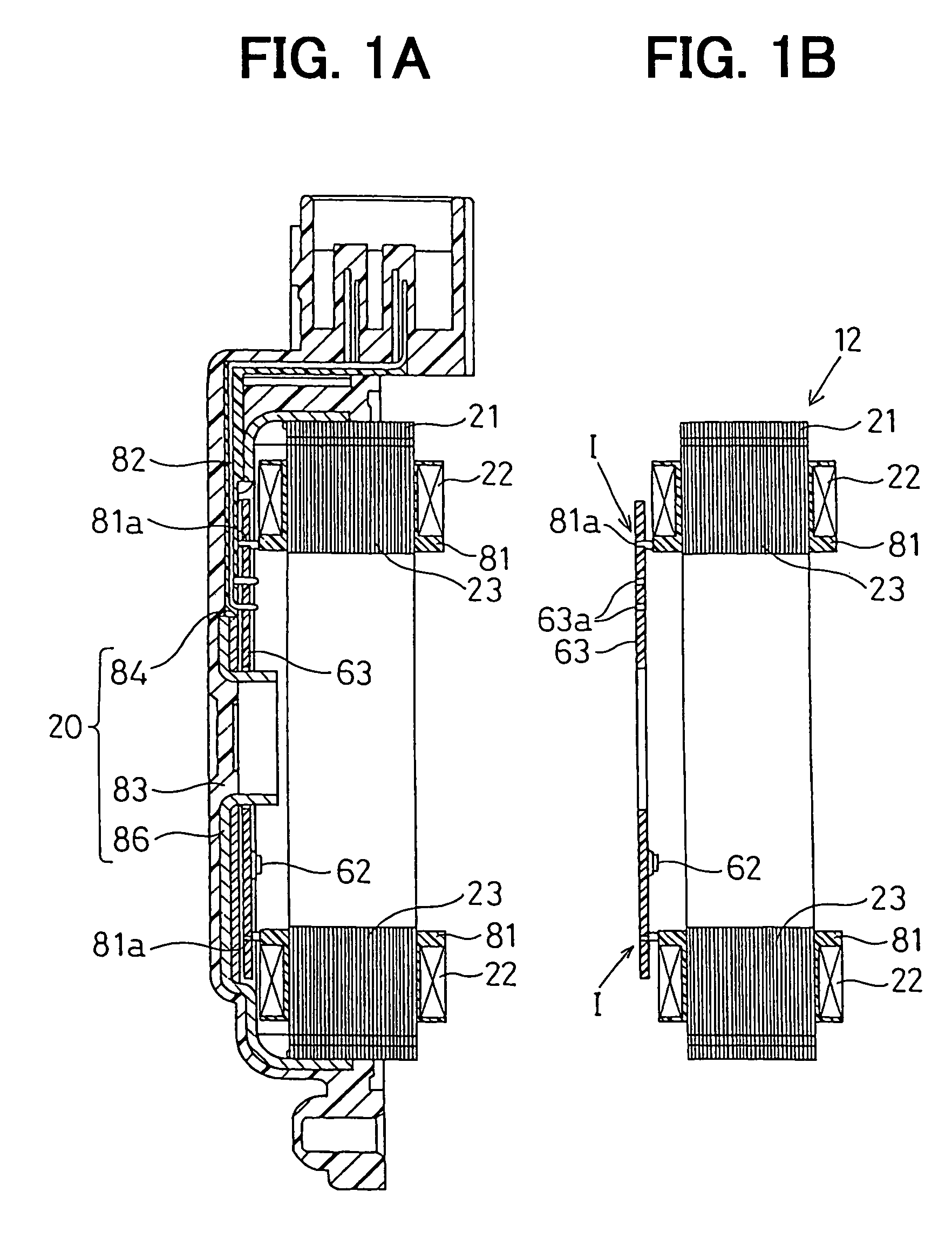
The present invention provides an accurate and affordable brushless synchronous motor that can be manufactured at high productivity. The motor includes a stator with phase coils, a rotor with a permanent magnet, an encoder, a magnetic sensor, and a circuit board. The circuit board connects the phase coils with the power supply means, and the magnetic sensor is directly fixed to the circuit board. The motor may also include bobbins to support the phase coils, a resinous member, stator and sensor terminals, and a housing made of resinous material with a metal ring to support the stator and rotor. The motor may further include a smaller air gap between the stator and rotor to increase output power.

Problems solved by technology

Thus, only the circuit board and the phase coils intervene between the magnetic sensor and the stator core, so that dimensional variation can be effectively limited.

Method used


Image

  • Brushless synchronous motor
  • Brushless synchronous motor
  • Brushless synchronous motor

Examples


Embodiment Construction

[0031]A brushless synchronous motor according to a preferred embodiment of the present invention will be described with reference to FIGS. 1–15.

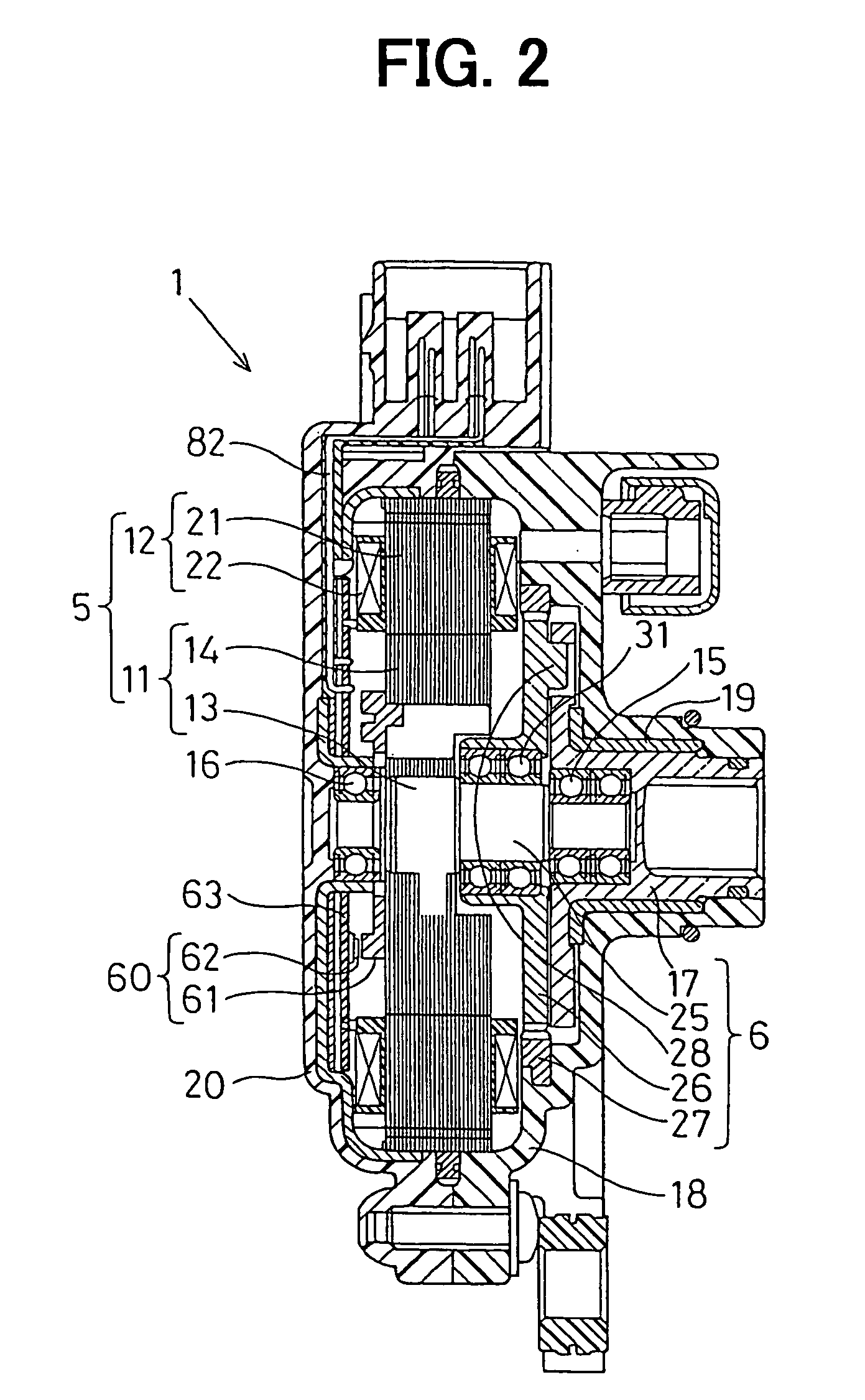
[0032]Such a brushless motor is applied to a gear shift range changing system. The shift range changing system includes a rotary actuator 1 shown in FIG. 2, an automatic transmission unit 2 shown in FIG. 3 and a shift range changing unit 3, which includes a parking mechanism 4, as shown in FIG. 4.

[0033]The rotary actuator 1 operates the shift range changing unit 3. The rotary actuator 1 includes a brushless synchronous motor 5, a speed reduction unit 6 and an encoder 60. The brushless synchronous motor 5 is a switched reluctance motor (SR motor) that is not equipped with a permanent magnet.

[0034]The motor 5 includes a rotor 11 and a stator 12, which is disposed to be coaxial with the rotor 11. The rotor 5 includes a rotary shaft 13 and a rotor core 14. The rotary shaft 13 is supported by a pair of roller bearings 15, 16 at the front (right i...


PUM


Abstract

A brushless synchronous motor includes a stator having a plurality of phase coils, a rotor disposed opposite the stator, a magnetic sensor for detecting a rotation angle of the rotor, a power supply circuit connected to the phase coils, a control circuit for controlling the power supply circuit so that the motor rotates synchronously. In the above motor, a circuit board includes a wiring circuit connecting the phase coils with the power supply circuit, and the magnetic sensor is directly fixed to the circuit board so that dimensional variation of the magnetic sensor relative to the stator can be minimized.

Description

CROSS REFERENCE TO RELATED APPLICATION[0001]The present application is based on and claims priority from Japanese Patent Application 2004-106463, filed Mar. 31, 2004, the contents of which are incorporated herein by reference.BACKGROUND OF THE INVENTION[0002]1. Field of the Invention[0003]The present invention relates to a brushless synchronous motor that changes current supply to a plurality of phase-coils based on the rotation angle of a rotor detected by an encoder.[0004]2. Description of the Related Art[0005]In a brushless synchronous motor having a plurality of phase coils, current supply is shifted from one to another of the phase coils according to the rotation angle. The rotation angle is detected by an encoder that is composed of a rotor on which a permanent magnet is mounted and a magnetic sensor element such as a hall IC element fixed on a circuit board. Such a magnetic sensor element detects magnetic flux provided by the permanent magnet, as disclosed in JP-A-2004-48908 ...

Claims


Application Information

Patent Timeline
Patent Type & Authority Patents(United States)
IPC IPC(8): H02K21/12F16H61/32G01D5/245H02K3/38H02K3/46H02K3/50H02K5/173H02K5/22H02K11/00H02K19/10H02K29/08H02P1/18
CPCH02K19/103H02K29/08F16H2061/326Y10S310/06H02K11/215
Inventor KIMURA, KIYOSHIITOH, TAKUYOSHIYAMA, SHIGERU
Owner DENSO CORP
Learn More