
Roadway incursion alert system

a technology of incursion alert and road, applied in the direction of traffic signals, instruments, roads, etc., can solve the problems of insufficient workers, insufficient distance over which the warning may be heard or seen, and inability to adapt to one type of safety icon, etc., to achieve the effect of extending the communication range and facilitating workers to determin

Inactive Publication Date: 2007-06-12
LOGIC SYST
View PDF25 Cites 46 Cited by
  • Summary
  • Abstract
  • Description
  • Claims
  • Application Information

AI Technical Summary

Benefits of technology

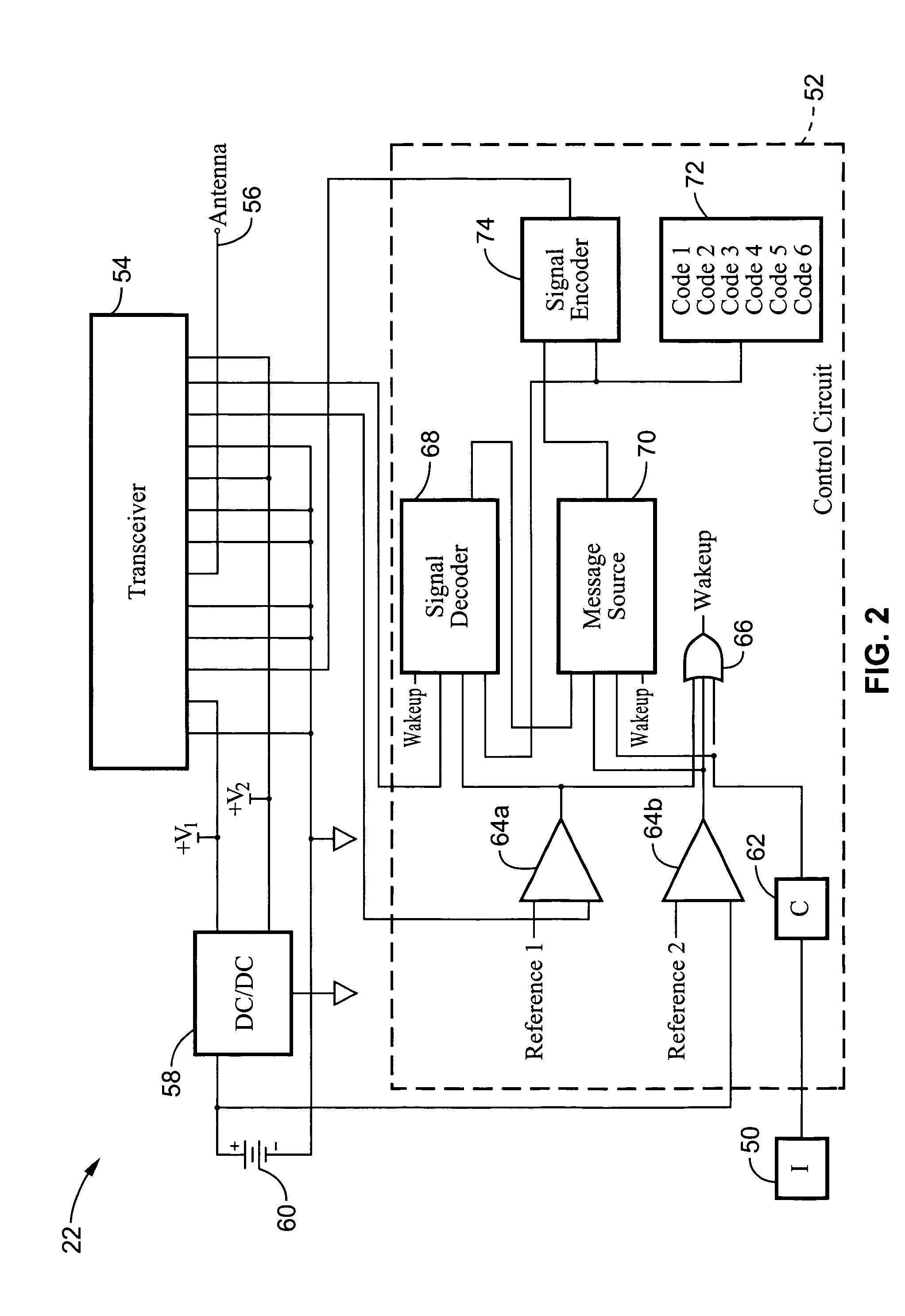
[0015]The incursion detection devices are adapted to detachably couple to structures or safety icons that may be positioned proximal to a roadway, and they communicate with one or more remote receivers over a wireless communications link. It will be appreciated that a wireless link allows for the flexible placement of the incursion detection units without concern for cord routing.
[0017]Each incursion detector unit may be implemented as either a transmitter or a transceiver. Implementing an incursion detection device as a transceiver can provide additional benefits, wherein selective repeating of the incursion alert signals from other incursion transmitters or transceivers toward at least one incursion receiver unit can be performed to extend the range of communication. Using transceiver units as repeaters is beneficial in that the incursion detectors reporting an alert signal to a receiver may span an extended distance while being less subject to signal loss because of terrain, line of sight or other obstructions. Although the devices may be implemented as either transmitter units or transceiver units, the incursion sensing devices will be herein referred to as incursion detectors.
[0018]Optionally, the incursion detectors may include a local area alert device, such as a light output, or sound, making it easier for workers to determine which incursion detector is generating, or generated, a particular alert as annunciated by an incursion receiver unit.
[0045]A further aspect of the invention is coupling a tilt sensor to the incursion detector, detecting a change in orientation of the incursion detector by the tilt sensor, and preventing communication of an alert signal when the tilt sensor detects a change in orientation of the incursion detector prior to an impact.
[0051]Another aspect of the invention is detecting a change in orientation of the incursion detector by the tilt sensor and preventing communication of an alert signal when the tilt sensor detects a change in orientation of the incursion detector prior to an impact.

Problems solved by technology

Existing incursion devices may only be adapted to one type of safety icon or have a limitation such as range or line of sight for transmitting a warning signal.
Unfortunately, construction sites are often extremely high noise environments in which alerting sounds, and / or lighting, positioned more than a few yards away may not be noticed by busy construction crews.
Further exacerbating the alert cognition problem, many workers wear noise attenuating hearing protection to minimize the noise hazard to which their ears are subjected.
The distance over which the warning may be heard, or seen, may be insufficient to allow workers to determine the cause of the alert and to extract themselves and others from danger.
As a result, even with incursion detectors available, many workers are struck by oncoming vehicles every year.
Distance, line of sight, and interference from equipment or structures are limitations of existing incursion detectors that must be taken into account when deploying these systems.
False signals also decrease effectiveness of these systems.
Connections and switches are susceptible to human error or accidental deactivation.
Extra time required to position and verify operation of existing safety devices further exposes workers to traffic hazards and lowers project productivity.
Consequently, since existing systems can only reliably communicate warnings over a short distance, road construction personnel are subject to increased risk of injury or death.

Method used


Image

  • Roadway incursion alert system
  • Roadway incursion alert system
  • Roadway incursion alert system

Examples


Embodiment Construction

[0066]Referring more specifically to the drawings, for illustrative purposes the present invention is embodied in the apparatus generally shown in FIG. 1 through FIG. 8. It will be appreciated that the apparatus may vary as to configuration and as to details of the parts, and that the method may vary as to the specific steps and sequence, without departing from the basic concepts as disclosed herein.

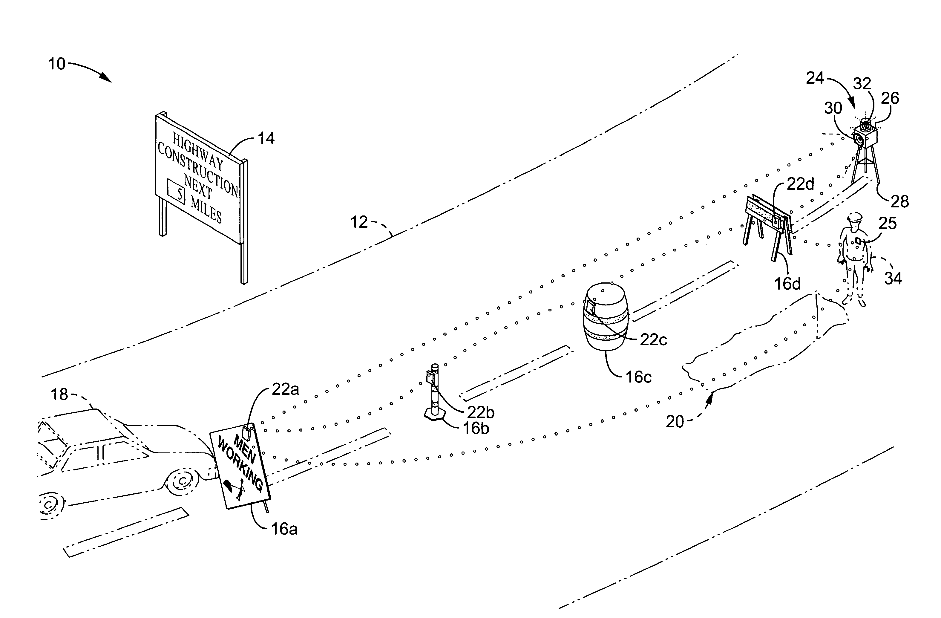
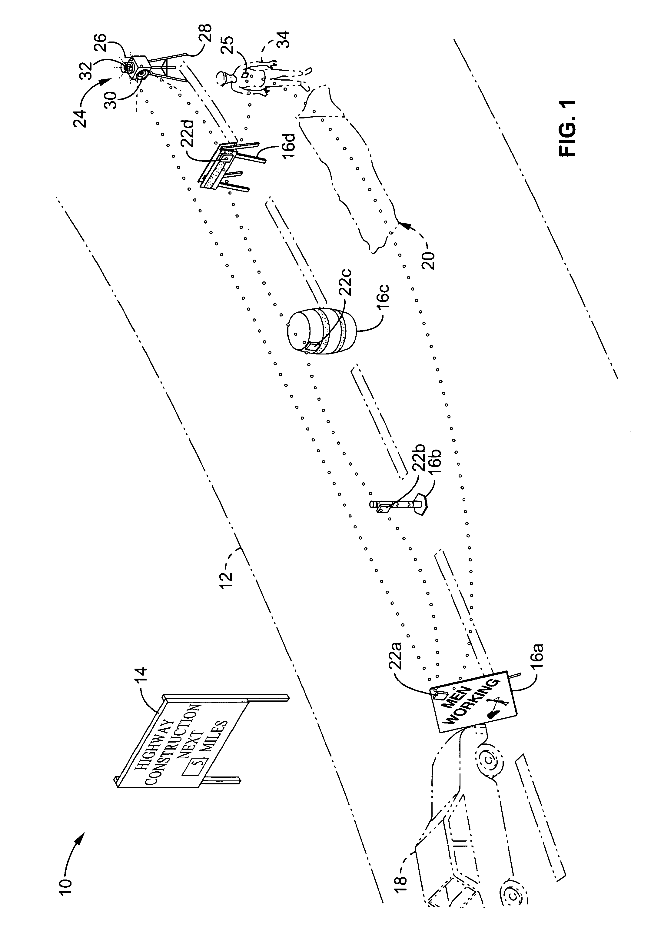
[0067]FIG. 1 exemplifies a typical roadway construction situation 10, showing a roadway 12 with a construction sign 14 and a series of traffic icons 16a–16d blocking off a closed lane. Icon 16a is a roadway sign, 16b is a pylon, 16c is a traffic barrel and 16d is a barricade and are examples of typical safety icons for routing and controlling vehicular traffic. In this situation, a vehicle 18 is shown impacting traffic icon 16a, which may be considered as an incursion of the vehicle into the closed lane providing a safety zone for the roadway workers near construction area 20. Usually su...


PUM


Abstract

An apparatus and method for generating incursion alerts in response to incursion events detected by incursion detector units, attached to safety icons such as traffic cones and signage. The incursion detector units are activated by automatic activation sensors and remain activated for a period of time. Alerts are generated in response to impacts detected at the safety icons by an incursion detector and transmitted to one or more incursion receiver units which annunciate the alert with audio, lights, or tactile output to warn personnel of possibly impending danger. Alert signals are preferably repeated by other incursion detectors wherein the distance and conditions over which the alert signals may be communicated is extended. A validation circuit and tilt sensor filter out not incursion events such as wind tipping. The incursion detectors may generate area alerts, or personal alerts and can transmit operational status and alerts to discrete groups of receivers.

Description

CROSS-REFERENCE TO RELATED APPLICATIONS[0001]This application is a continuation-in-part of application Ser. No. 10 / 289,230 filed on Nov. 5, 2002 now U.S. Pat. No. 7,030,777, incorporated herein by reference in its entirety, which claims priority from U.S. provisional application Ser. No. 60 / 337,035 filed on Nov. 6, 2001, incorporated herein by reference in its entirety. This application also claims priority from U.S. provisional application Ser. No. 60 / 534,615 filed on Jan. 6, 2004, incorporated herein by reference in its entirety.STATEMENT REGARDING FEDERALLY SPONSORED RESEARCH OR DEVELOPMENT[0002]Not ApplicableINCORPORATION-BY-REFERENCE OF MATERIAL SUBMITTED ON A COMPACT DISC[0003]Not ApplicableNOTICE OF MATERIAL SUBJECT TO COPYRIGHT PROTECTION[0004]A portion of the material in this patent document is subject to copyright protection under the copyright laws of the United States and of other countries. The owner of the copyright rights has no objection to the facsimile reproduction...

Claims


Application Information

Patent Timeline
Patent Type & Authority Patents(United States)
IPC IPC(8): G08G1/01
CPCG08G1/01G08G1/0955G08G1/164
Inventor NELSON, CRAIGBOS, ROBERT
Owner LOGIC SYST
Learn More