Method and apparatus for multiplexing and demultiplexing variable-length packets

a variable-length packet and multi-layer technology, applied in data switching networks, store-and-forward switching systems, high-level techniques, etc., can solve the problems of reducing bandwidth efficiency, reducing transport efficiency, and reducing bandwidth efficiency, so as to reduce cost and maximize channel efficiency

Inactive Publication Date: 2007-06-12
ELECTRONICS & TELECOMM RES INST
View PDF17 Cites 24 Cited by
  • Summary
  • Abstract
  • Description
  • Claims
  • Application Information

AI Technical Summary

Benefits of technology

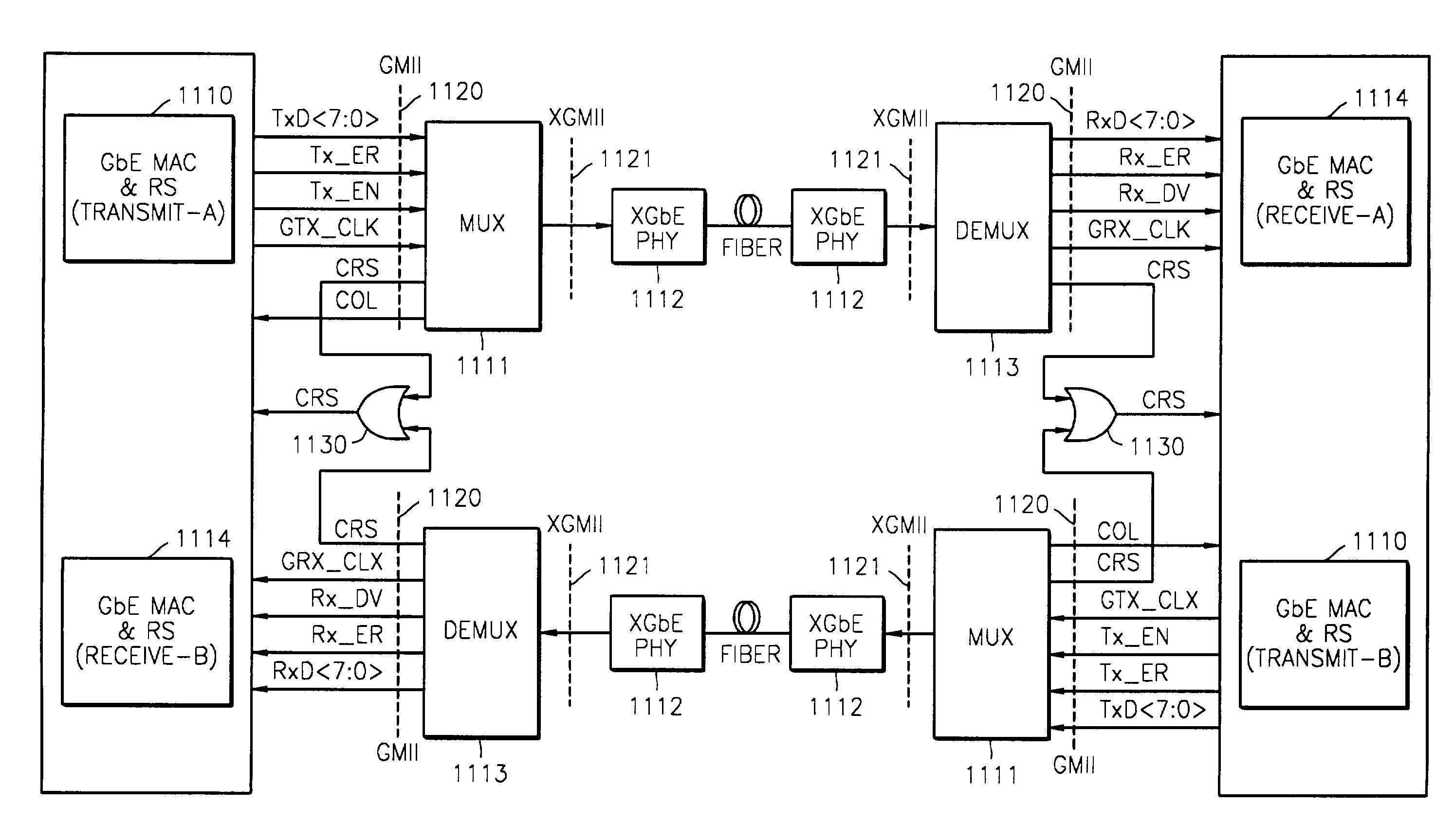
[0017]To solve the above-described problems, it is an object of the present invention to provide an apparatus and method for multiplexing and demultiplexing packets, in which cost is reduced by using a universal chip, i.e., by using a standard interface, and the efficiency of a channel is maximized through packet multiplexing.

Problems solved by technology

Moreover, due to the characteristics of TDM, an exclusive channel must be used, which decreases bandwidth efficiency.
Moreover, in this case, transport efficiency is decreased.
However, the above-described methods employ conventional TDM channels to transport packets, so bandwidth efficiency is decreased, and the methods cannot be applied to the multiplexing of low-speed Ethernet packets into a high-speed Ethernet packet.
However, it is difficult to apply this method to a case in which as in the Ethernet, packets have different lengths and different destinations.
Moreover, it is nearly impossible to directly apply this method to a demultiplexer when packet length variation is very large as in the Ethernet.
However, it is difficult to apply this method to a case in which an output packet also has a variable length as in the Ethernet.
As described above, conventional TDM methods decrease bandwidth efficiency.

Method used


Image

  • Method and apparatus for multiplexing and demultiplexing variable-length packets
  • Method and apparatus for multiplexing and demultiplexing variable-length packets
  • Method and apparatus for multiplexing and demultiplexing variable-length packets

Examples


Embodiment Construction

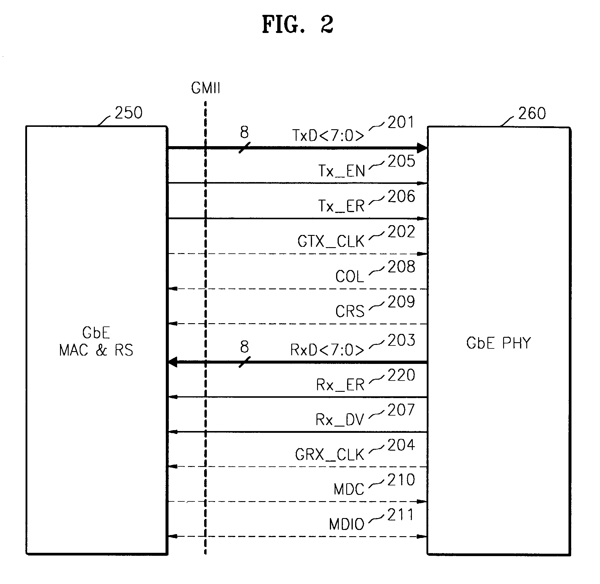
[0037]Hereinafter, preferred embodiments of the present invention will be described in detail with reference to the attached drawings.

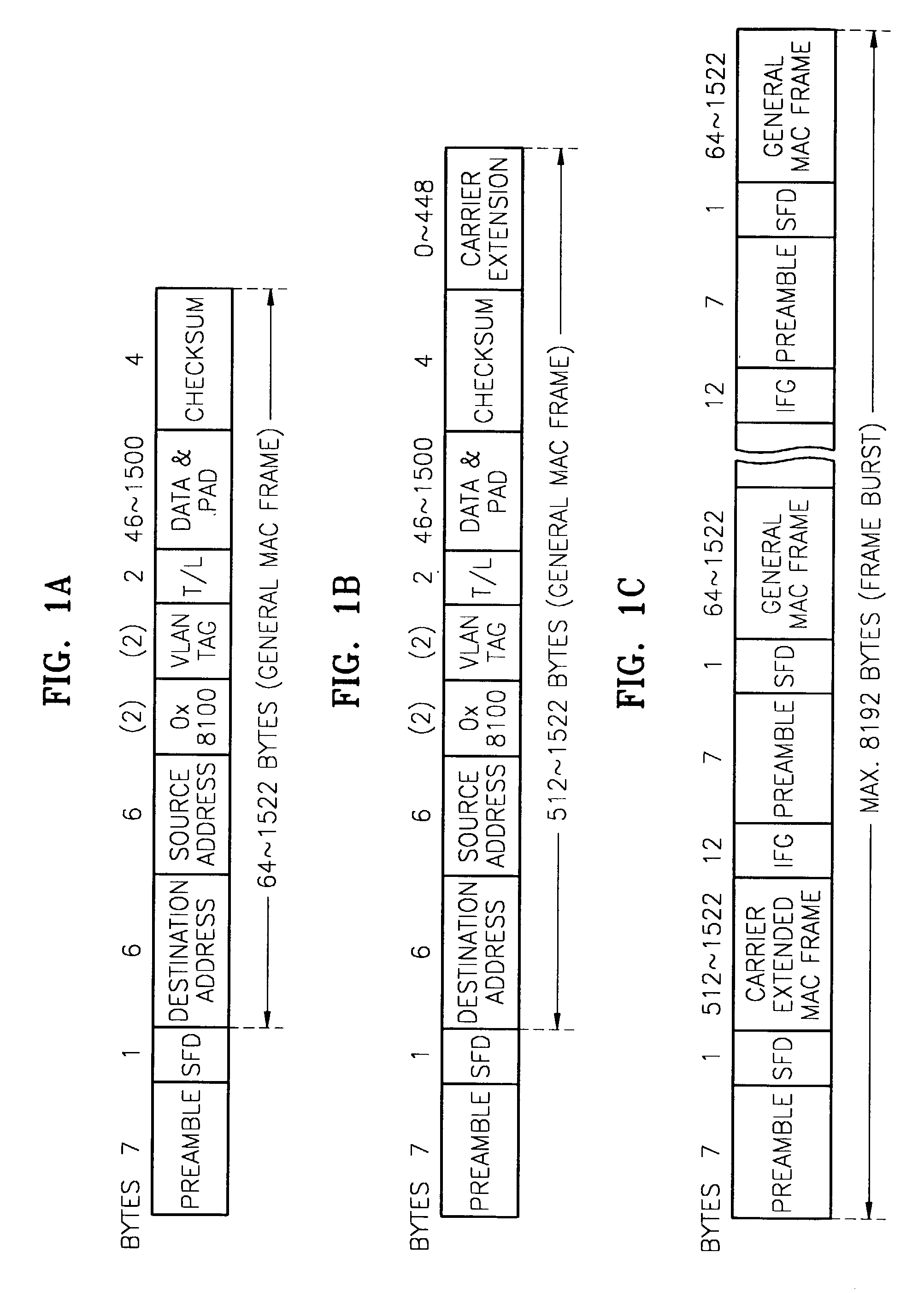
[0038]The structures and operations of Ethernet frames will be described in terms of standards defined by IEEE 802.3 with reference to FIGS. 1A through 1C.

[0039]FIG. 1A shows the structure of a general Ethernet media access control (MAC) frame. If a preamble of 7 bytes, in which 1 and 0 are sequentially and alternately repeated like 10101010, is followed by 10101011, i.e., a Start of Frame Delimiter (SFD), the SFD is recognized, and an MAC frame starts. The SFD is followed sequentially by a 6-byte destination address (DA) and a 6-byte source address (SA). In case of a virtual local area network (VLAN), the source address is followed sequentially by a 2-byte 0×8100 value indicating a VLAN tag and a 2-byte VLAN tag.

[0040]In the next two bytes is recorded type / length information. Thereafter, a variable-length data and pad field of 46–1500 bytes is contin...


PUM


Abstract

Provided are a method and apparatus for multiplexing and demultiplexing variable-length high-speed packets. According to the method and apparatus, a plurality of one-gigabit Ethernet frames are multiplexed into a single 10-gigabit Ethernet frame and the single 10-gigabit Ethernet frame is demultiplexed into the plurality of one-gigabit Ethernet frames. In order to process variable-length high-speed packets, packet multiplexing instead of simple TDM is used and a larger input bandwidth than an output bandwidth is used, so that a statistical multiplex effect is accomplished. In addition, standard interface is used for input and output interface, so existing universal chips can be used.

Description

BACKGROUND OF THE INVENTION[0001]1. Field of the Invention[0002]The present invention relates to a method and apparatus for multiplexing and demultiplexing variable-length high-speed packets, and more particularly, to a method and apparatus for multiplexing a plurality of one-gigabit Ethernet media access control (MAC) frames into a single 10-gigabit Ethernet frame and demultiplexing the single 10-gigabit Ethernet frame into the plurality of one-gigabit Ethernet MAC frames.[0003]2. Description of the Related Art[0004]Packet multiplexing is technology through which a transmitter converts a plurality of packets into a high-speed packet and transmits it to a receiver, and the receiver converts the received high-speed packet into the original plurality of low-speed packets and sent them to a destination.[0005]In realizing such technology, it seems most practical to employ time division multiplexing (TDM) to multiplex low-speed input streams into a high-speed data stream. However, in the...

Claims


Application Information

Patent Timeline
Patent Type & Authority Patents(United States)
IPC IPC(8): H04J3/04H04L12/56H04J3/02H04L12/413
CPCH04J3/047H04L12/40032H04L12/413H04L12/56H04L12/40039Y02B60/35Y02D30/50H04J3/02
Inventor KANG, SUNG-SOOKANG, TAE-KYUJUNG, HAE-WONLEE, HYEONG-HO
Owner ELECTRONICS & TELECOMM RES INST
Why Eureka
Try Eureka