Stereoscopic three-dimensional metrology system and method

Active Publication Date: 2007-06-12
ONTO INNOVATION INC
View PDF4 Cites 34 Cited by
  • Summary
  • Abstract
  • Description
  • Claims
  • Application Information

AI Technical Summary

Benefits of technology

[0009]Embodiments of the present invention overcome the above-mentioned and various other shortcomings of conventional technology, providing a stereoscopic three-dimensional optical metrology system and method of accurately measuring the location of physical features on a test article in a manner that is fast and robust to surface contour discontinuities. As set forth in

Problems solved by technology

Each of the conventional methods suffers from significant deficiencies at least with respect to measurement applications: requiring high speed and parallelized information acquisition; in which surface contours may include steep sloping surfaces or surface discontinuities; and in which it is desirable to avoid expensive, high accuracy motion stages.
The structured lighting and interferometric methods, for example, provide poor results with respect to measuring features on a test article having steeply sloping surfaces or surface discontinuities.
The laser range finding method is slow and generally inaccurate.
These systems and methods can be highly precise, but are generally limited in at least the following respects.
Accordingly, laser interferometric techniques do not permit omission of uninteresting regions of the test article; this slows performance.
Further, steeply pitched surfaces or surface discontinuities (e.g., sharp vertical edges or one object disposed on top of another) can result in erroneous dat

Method used


Image

  • Stereoscopic three-dimensional metrology system and method
  • Stereoscopic three-dimensional metrology system and method
  • Stereoscopic three-dimensional metrology system and method

Examples


Embodiment Construction

[0034]As set forth in detail below, aspects of the present system and method may minimize or eliminate the foregoing significant deficiencies of conventional metrology approaches, specifically: (1) speed or throughput rate limitations; (2) measurement difficulties associated with surface discontinuities; and (3) reliance upon the accurate motion of stages.

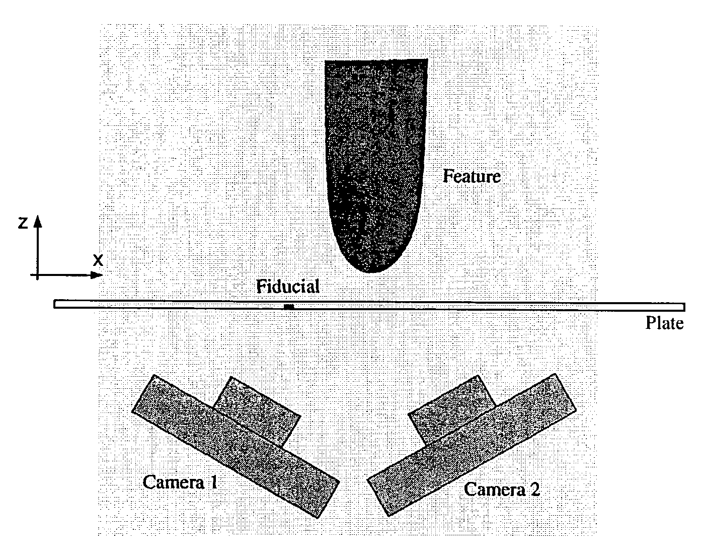
[0035]The exemplary embodiments acquire field measurements, not point measurements. In particular, each imaged field of view may produce position measurements for every identified feature in a view, and accordingly, a high degree of parallelism may be achieved. As a consequence, position measurement throughput is significantly greater than can be attained using point measurement methods such as laser range finding. Further, unlike the interferometric strategies and the structured light approach, a system and method operative in accordance with the present disclosure do not require image location continuity to ensure a tie to an est...


PUM


Abstract

A stereoscopic three-dimensional optical metrology system and method accurately measure the location of physical features on a test article in a manner that is fast and robust to surface contour discontinuities. Disclosed embodiments may image a test article from two or more perspectives through a substantially transparent fiducial plate bearing a fiducial marking; camera viewing angles and apparent relative distances between a feature on a test article and one or more fiducials may enable accurate calculation of feature position.

Description

[0001]This application claims the benefit of U.S. provisional application Ser. No. 60 / 346,447 entitled “APPARATUS FOR STEREOSCOPIC THREE-DIMENSIONAL METROLOGY,” filed Dec. 28, 2001.FIELD OF THE INVENTION[0002]Aspects of the present invention relate generally to metrology, and more particularly to a system and method of accurately measuring the three-dimensional location of physical features on a test article in a manner that is fast and robust to surface contour discontinuities.DESCRIPTION OF THE RELATED ART[0003]Several three-dimensional (3D) optical metrology techniques are generally known and currently practiced. These methods include structured lighting, moire and laser interferometry, laser range finding, and a conventional two camera approach. Each of the conventional methods suffers from significant deficiencies at least with respect to measurement applications: requiring high speed and parallelized information acquisition; in which surface contours may include steep sloping ...

Claims


Application Information

Patent Timeline
IPC IPC(8): G06K9/00G01B11/00G01B11/03G01B11/245G01B11/25G01C11/06H01L21/66H05K13/00
CPCG01B11/245G01B11/254G01C11/06G06T7/0057H05K13/0015G06T7/521
Inventor SNOW, DONALD B.KRAFT, RAYMOND H.STROM, JOHN T.
Owner ONTO INNOVATION INC
Why Eureka
Try Eureka