Multi-circuit refrigerant cycle with dehumidification improvements

a refrigerant cycle and multi-circuit technology, applied in the field of multi-circuit refrigerant systems, can solve problems such as design challenges for refrigerant cycle designers, and achieve the effect of improving component reliability and improving system efficiency

Active Publication Date: 2007-06-19
CARRIER CORP
View PDF3 Cites 22 Cited by
  • Summary
  • Abstract
  • Description
  • Claims
  • Application Information

AI Technical Summary

Benefits of technology

[0006]In one of the disclosed embodiments of this invention, a multi-circuit refrigerant system incorporates at least two circuits and at least one of those circuits having a reheat coil in the reheat branch of the circuit. The circuits are inter-related in some manner or, in other words, have some means of communication to provide interaction between the circuits. In one embodiment, a flow control valve(s) is installed on the inter-connecting line(s) providing communication between the circuits, such that the amount of refrigerant contained in each circuit can be controlled depending on the environmental conditions, unit operating parameters, external sensible and latent load demands, and a mode of operation for each circuit. In another embodiment, a single heat exchanger is utilized for multiple reheat coils so that the properly configured circuits are communicating through the heat transfer interaction to each other and to the air stream supplied to the conditioned space. In yet another embodiment, a control and a corresponding system design are provided to allow some of the circuits to function in other operational regimes, different from commonly known conventional cooling and conventional dehumidification modes of operation. In one of the described configurations, a bypass line around the condenser is provided to allow such system operational flexibility. In yet another embodiment, the multi-circuit system control unit limits system operation in such a way that it never operates some of the circuits in the conventional cooling mode and some of the circuits in the conventional reheat mode, allowing for enhanced system efficiency and improved component reliability.
[0007]It has to be noted that this invention is not referenced to any particular reheat concept but rather provides advantages for any system designed for dehumidification and / or cooling through interaction between the circuits and enhanced control logic.

Problems solved by technology

This has presented design challenges to refrigerant cycle designers.

Method used


Image

  • Multi-circuit refrigerant cycle with dehumidification improvements
  • Multi-circuit refrigerant cycle with dehumidification improvements
  • Multi-circuit refrigerant cycle with dehumidification improvements

Examples


Embodiment Construction

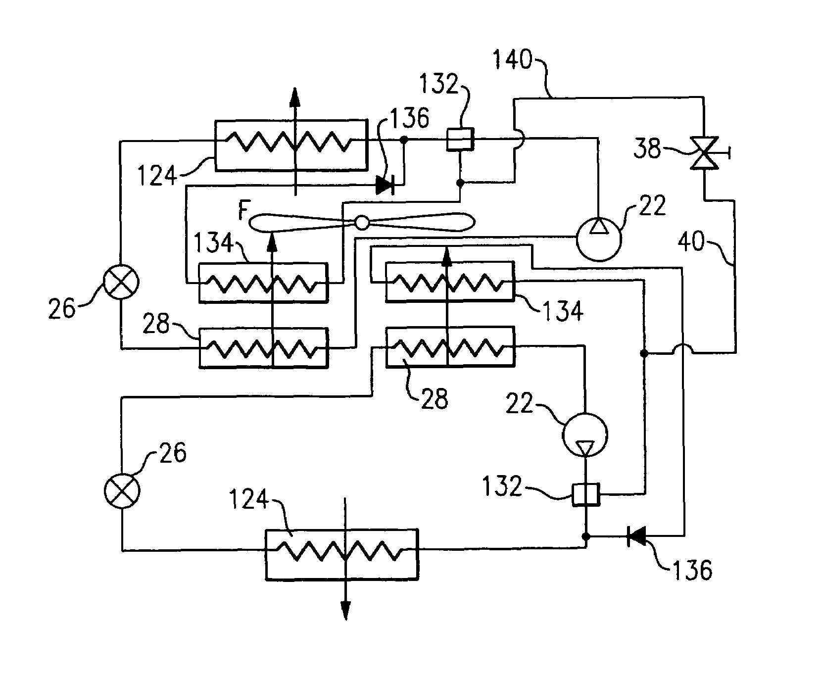
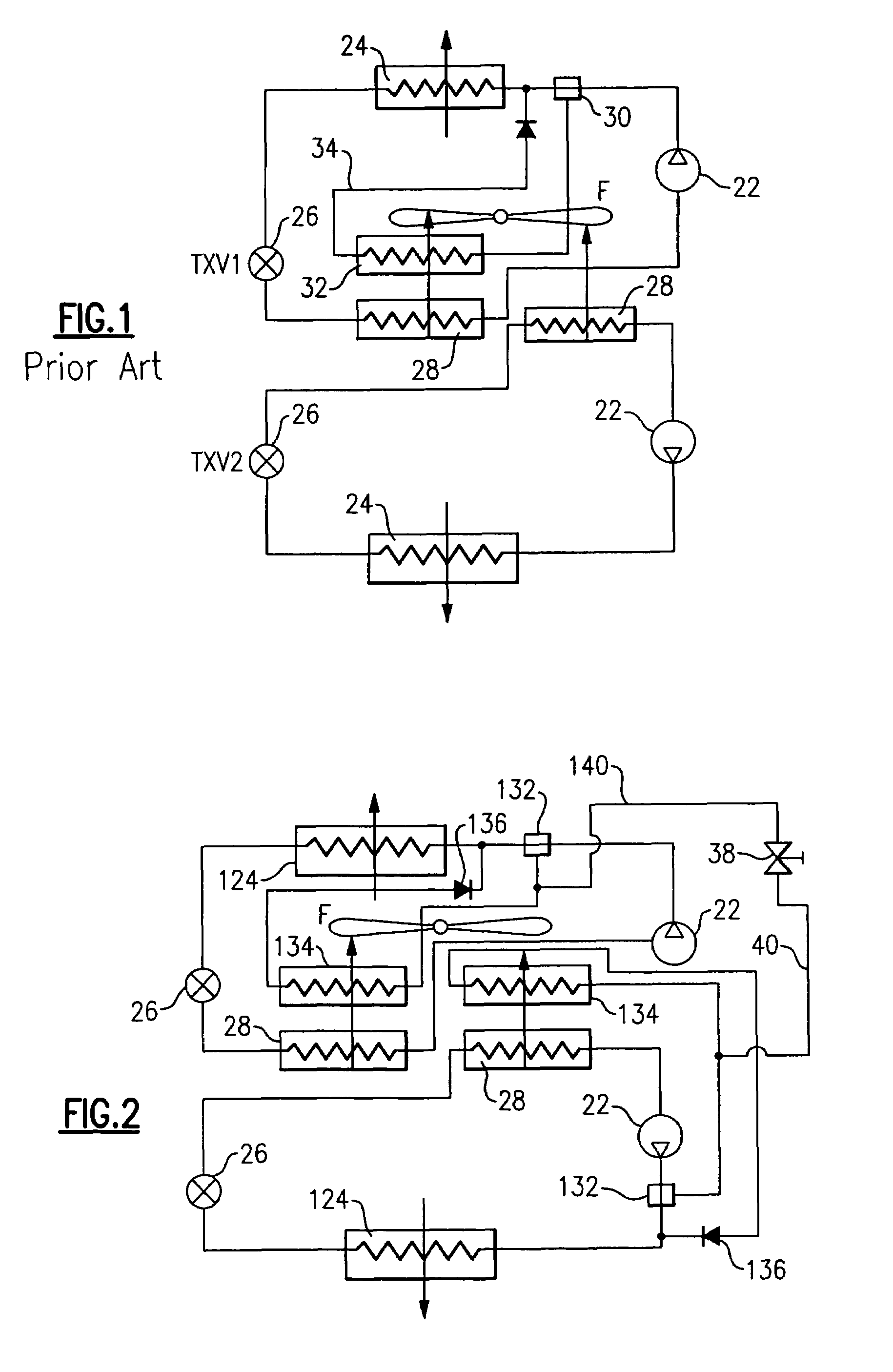
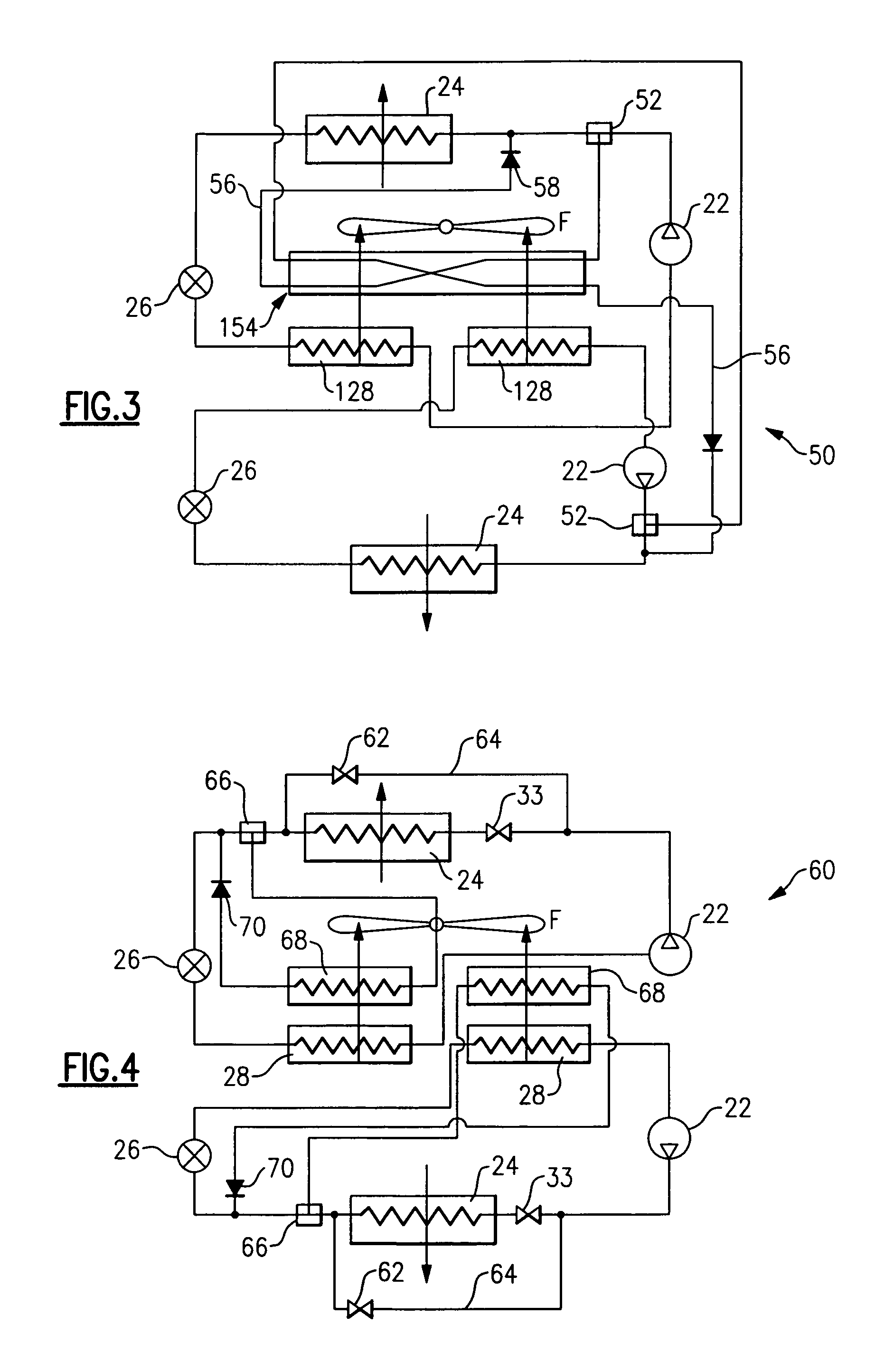
[0013]A prior art refrigerant system 20 is illustrated in FIG. 1 as a two-circuit system, with two discrete circuits that do not communicate with each other. Each of two circuits includes a compressor 22, a condenser 24, a main expansion device 26, and an evaporator 28. As known, indoor air to be conditioned passes over the evaporator 28 to be cooled and typically dehumidified when the refrigerant system 20 is in operation. One of the circuits is provided with a reheat coil 32. A selectively operable three-way valve 30 is opened to pass at least a portion of refrigerant through the reheat coil 32 when humidity of the conditioned space is still higher than desired, but temperature of that space falls below the comfort level, requiring the reheat function to be activated. Although only one of many known reheat schematics is shown for illustration purposes, a person ordinarily skilled in the art can envision other reheat concepts implemented as well. In the schematic shown on FIG. 1, t...


PUM


Abstract

Multi-circuit refrigerant systems are provided with better control over a dehumidification function. In one embodiment, system circuits have means of communication with each other through connecting lines and flow control devices operable on demand. In another embodiment, a single reheat heat exchanger is utilized for both circuits, ensuring heat transfer interaction between the circuits. In yet another embodiment, a control unit operates refrigerant circuits in such a way that if some circuits are in a reheat mode, the remaining circuits are either shut off or are in an enhanced reheat mode.

Description

BACKGROUND OF THE INVENTION[0001]This application relates to multi-circuit refrigerant systems that are capable of executing multiple modes of operation. Typically, these systems have a reheat coil(s) incorporated into the system design to provide a reheat function, and additional control means capable of alternating between operational regimes independently for each circuit in response to environmental conditions and load demands.[0002]Refrigerant cycles are utilized to control the temperature and humidity of air in various environments to be conditioned. Typically, a refrigerant is compressed in a compressor and delivered to a condenser. In the condenser, heat is exchanged between outside ambient air and the refrigerant. From the condenser, the refrigerant passes to an expansion device in which the refrigerant is expanded to a lower pressure and temperature, and then to an evaporator. In the evaporator, heat is exchanged between the refrigerant and the indoor air, to condition the...

Claims


Application Information

Patent Timeline
Patent Type & Authority Patents(United States)
IPC IPC(8): F25B49/00F24F11/00F25D17/06F24F3/153F25B41/00F25B41/04F25D21/06
CPCF24F3/153F25B41/04F25B2400/0403F25B2400/06F25B41/20F25B41/24
Inventor TARAS, MICHAEL F.LIFSON, ALEXANDER
Owner CARRIER CORP
Why Eureka
Try Eureka