Apparatus and method for using vehicle status information in safety restraint systems

a technology for safety restraints and apparatuses, applied in the direction of pedestrian/occupant safety arrangements, process and machine control, instruments, etc., can solve the problems affecting and posing a potential danger to the technician or the person handling the acm. , to achieve the effect of reducing the number of inappropriate activations and deployments, improving the operation of vehicle safety systems

Active Publication Date: 2007-06-19
ROBERT BOSCH CORP +1
View PDF14 Cites 28 Cited by
  • Summary
  • Abstract
  • Description
  • Claims
  • Application Information

AI Technical Summary

Benefits of technology

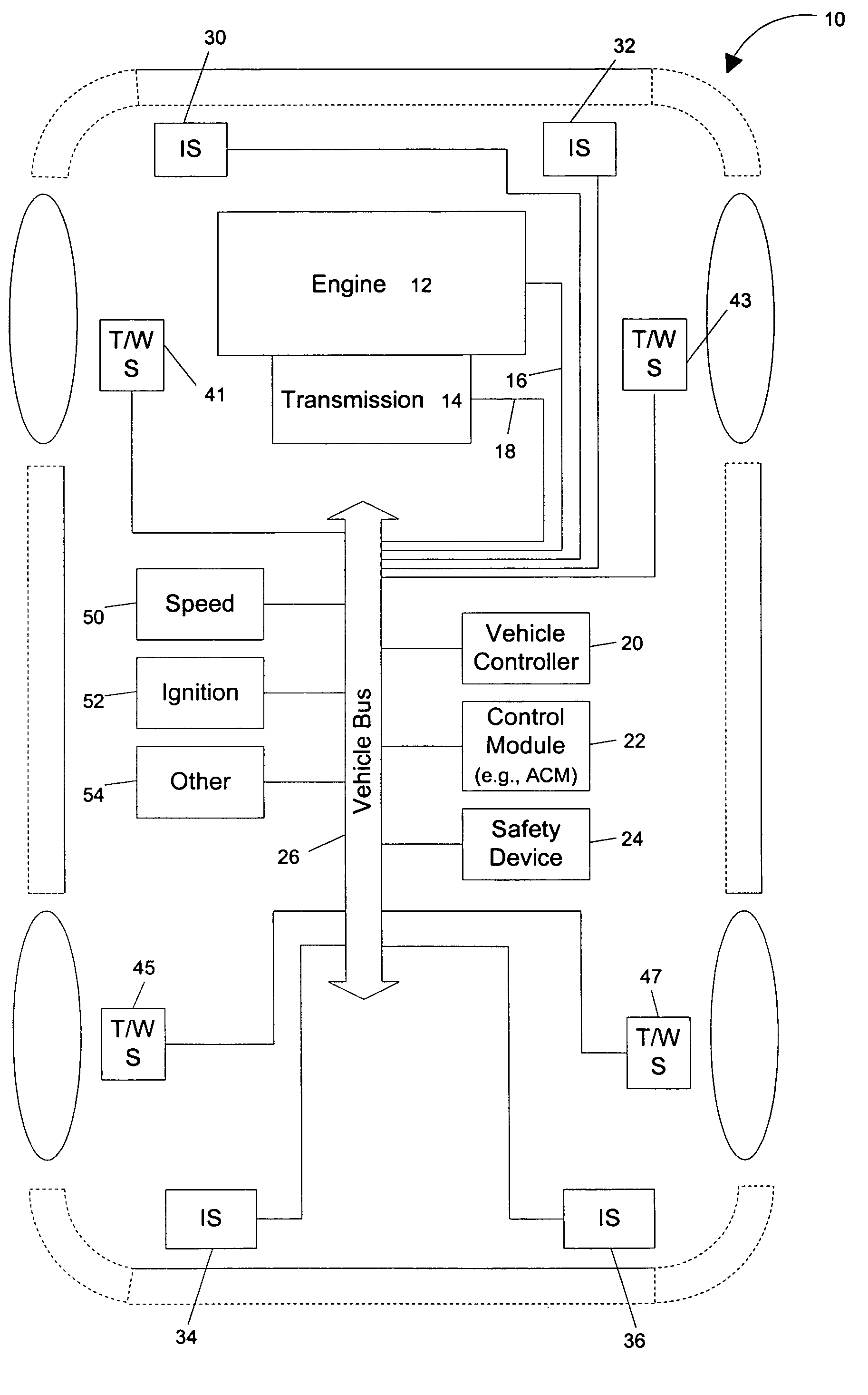
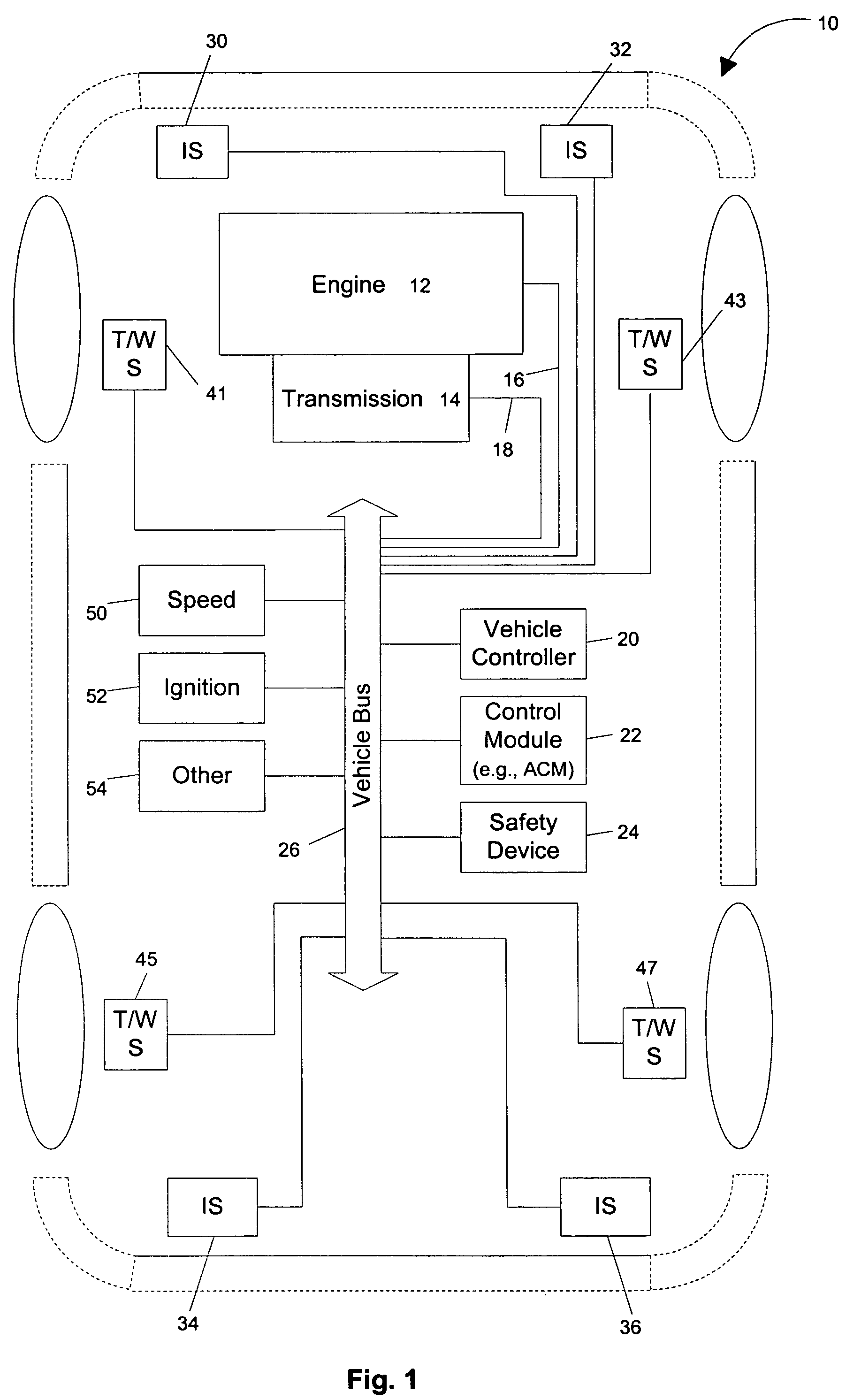
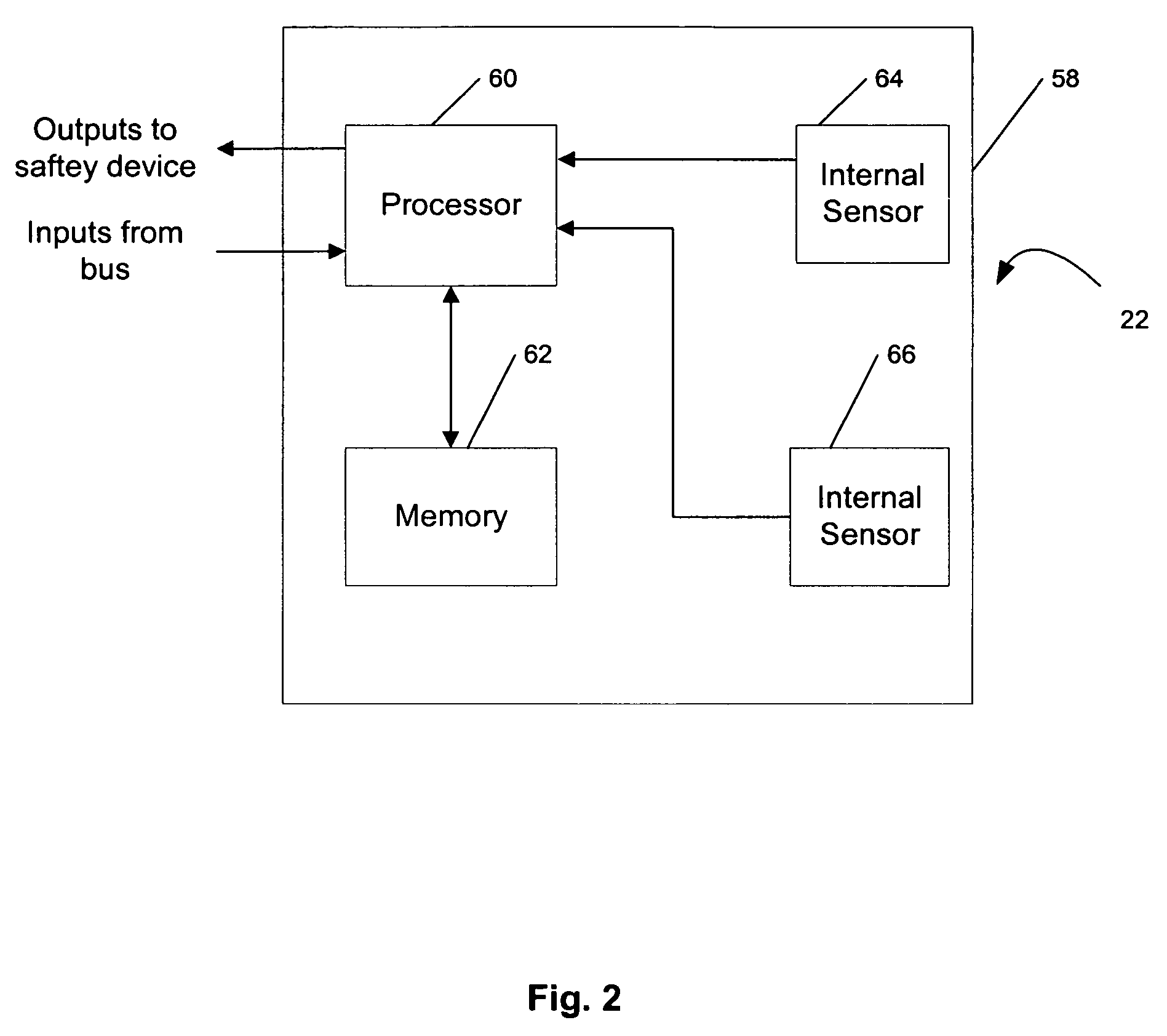
[0004]The inventor has learned that with certain airbag control and sensing modules (“ACMs”) with integrated sensors it is possible for a person during testing, installation, or servicing to inadvertently cause the ACM to activate or deploy airbags (or other safety devices) connected to the ACM. In essence, handling of the ACM by a person, such as by rotating or turning over the housing, can cause the ACM to believe that a rollover condition has occurred. Deployment of air bags or other safety devices in such circumstances poses a potential danger to the technician or person handling the ACM. Accordingly, there is a need to improve the operation of vehicle safety systems so that inappropriate activations and deployments may be reduced.

Problems solved by technology

Deployment of air bags or other safety devices in such circumstances poses a potential danger to the technician or person handling the ACM.
The supplemental sensors do not, however, guarantee that the air bag will only be deployed when a situation requiring its activation truly exists.
Even if the weight and position sensors indicate that the air bag should be disabled, the sensors are only being used to indicate the correct operation of the safety system during a possible collision and not that the operation of the safety system is unneeded since a collision has not actually occurred.

Method used


Image

  • Apparatus and method for using vehicle status information in safety restraint systems
  • Apparatus and method for using vehicle status information in safety restraint systems
  • Apparatus and method for using vehicle status information in safety restraint systems

Examples


Embodiment Construction

[0017]Before embodiments of the invention are explained in detail, it is to be understood that the invention is not limited in its application to the details of the examples set forth in the following description or illustrated in the drawings. The invention is capable of other embodiments and of being practiced or carried out in a variety of applications and in various ways. Also, it is to be understood that the phraseology and terminology used herein is for the purpose of description and should not be regarded as limiting. The use of “including,”“comprising,” or “having” and variations thereof herein is meant to encompass the items listed thereafter and equivalents thereof as well as additional items. Unless the context indicates otherwise, the terms “mounted,”“connected,” and “coupled” are used broadly and encompass both direct and indirect mounting, connecting, and coupling. Further, “connected” and “coupled” are not restricted to physical or mechanical connections or couplings....


PUM


Abstract

Method and devices for disabling detection of a safety system activation condition. One embodiment of the invention provides a method that includes disregarding information from a first set of sensors when detection of a safety system activation condition is disabled; determining if information from a second set of sensors in available; when information from a second set of sensors is not available, generating a warning signal; when information from the second set of sensors is available, determining a value of the information from the second set of sensors; and when the value of the information from the second set of sensors indicates that a vehicle is in use, enabling detection of the safety system activation condition.

Description

RELATED APPLICATIONS[0001]The present application claims priority to U.S. provisional patent application Ser. No. 60 / 534,786 titled “APPARATUS AND MEHTOD FOR USING VEHICLE STATUS INFORMATION IN SAFETY RESTRAINTS SYSTEMS,” filed on Jan. 7,2004.FIELD OF THE INVENTION[0002]Embodiments of the invention generally relate to methods and devices used in automotive occupant safety systems. More specifically, embodiments of the invention relate to providing additional information to occupant safety systems to reduce the probability that such systems will be inappropriately activated.BACKGROUND OF THE INVENTION[0003]Modern land vehicles include a number of occupant safety devices including, for example, automatically tensioned seat belts, air bags, and rollover sensing systems. In the case of air bags, their deployment may be based on information from a variety of sensors such as speed sensors, accelerometers, and angle sensors. In some cases these sensors are located remotely from a processin...

Claims


Application Information

Patent Timeline
Patent Type & Authority Patents(United States)
IPC IPC(8): B60Q1/00B60R16/023B60R16/02B60R21/00B60R21/01B60R21/015
CPCB60R21/01B60R21/01566B60R21/01564B60R2021/01068B60R2021/01177
Inventor PAVLISH, DAVID L.
Owner ROBERT BOSCH CORP
Why Eureka
Try Eureka