Disc-shaped recording medium, manufacturing method thereof, and disc drive device

a technology of disc-shaped recording medium and manufacturing method, which is applied in the direction of data recording, combination recording, instruments, etc., can solve the problems of reducing the signal s/n (signal-to-noise) ratio and hence the signal quality, incurring much noise, and no good detrack characteristic, so as to reduce the influence of electromagnetic field, and good detrack characteristic

Inactive Publication Date: 2007-06-19
SONY CORP
View PDF12 Cites 5 Cited by
  • Summary
  • Abstract
  • Description
  • Claims
  • Application Information

AI Technical Summary

Benefits of technology

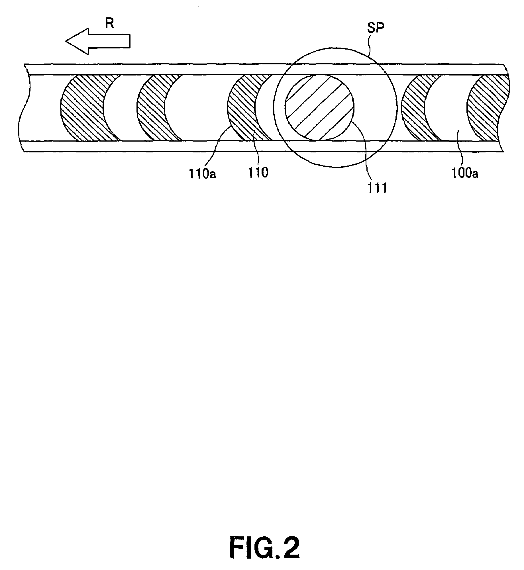
[0021]The aforementioned signal recorded to the above disk-shaped recording medium according to the present invention may be a recording pattern signal having a higher frequency component than a modulation transfer function (MTF) of the optical pickup head. Since there is recorded such a recording pattern having the higher frequency component than the modulation transfer function (MTF) of the optical pickup head, so it is possible to assure a good detrack characteristic at the time of disk playback without influence of the remaining nonuniform magnetization as in the initial state and influence of a drifting magnetic field caused by the uniform magnetization.
[0022]Also the above object can be attained by providing a method of producing a disk-shaped recording medium to be played in a disk drive unit which reproduces information recorded in the disk-shaped recording medium by an optical pickup head including a drive means which uses an electromagnetic force as the driving force, the method including, according to the present invention, the step of recording to the recording medium a signal which reduces the influence of an electromagnetic field applied by the optical pickup head. The signal recorded in the signal recording step is recorded by a magnetization in a direction of reducing the influence of the electromagnetic field applied by the optical pickup head.
[0023]In the above disk-shaped recording medium producing method according to the present invention, the influence of a leakage flux from the driving means in the optical pickup head is reduced, thereby permitting to lessen noises caused by a cross talk during information reproduction.
[0024]Also the above object can be attained by providing a disk drive unit which reproduces information recorded in a disk-shaped recording medium by an optical pickup head including a drive means which uses an electromagnetic force as the driving force, the apparatus including according to the present invention a recording means for recording to the disk-shaped recording medium a signal which reduces the influence of an electromagnetic field applied by the optical pickup head.
[0025]In the above disk drive unit according to the present invention, the signal recorded in the disk-shaped recording medium is a one recorded by magnetization oriented to reduce the influence of the magnetic field applied by the optical pickup head.
[0026]In the above disk drive unit according to the present invention, the influence of a leakage flux from the driving means in the optical pickup head is reduced, thereby permitting to lessen noises caused by a cross talk during information reproduction.

Problems solved by technology

The layers just formed are magnetized in different directions, which will cause noises when information is written to or read from the disk.
In a disk having a small track pitch, the remaining nonuniform magnetization will cause a cross talk which degrades the signal S / N (signal-to-noise) ratio and hence the signal quality.
However, the ultra-high resolution magneto-optical disk such as DWDD type disk, even if processed by the bulk erase method, incurs much noise during information recording or reproduction and shows no good detrack characteristic at the time of disk playback.

Method used


Image

  • Disc-shaped recording medium, manufacturing method thereof, and disc drive device
  • Disc-shaped recording medium, manufacturing method thereof, and disc drive device
  • Disc-shaped recording medium, manufacturing method thereof, and disc drive device

Examples


Embodiment Construction

[0053]The present invention will be described in detail concerning its embodiment below with reference to the accompanying drawings.

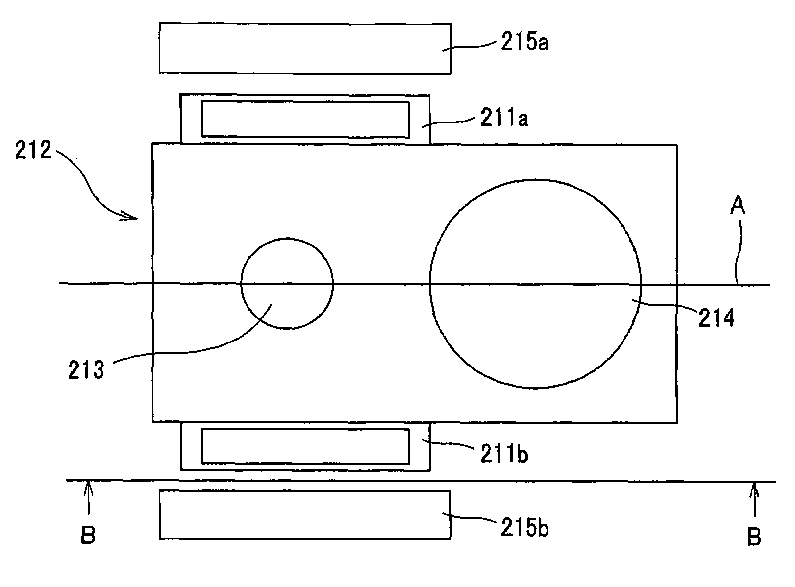
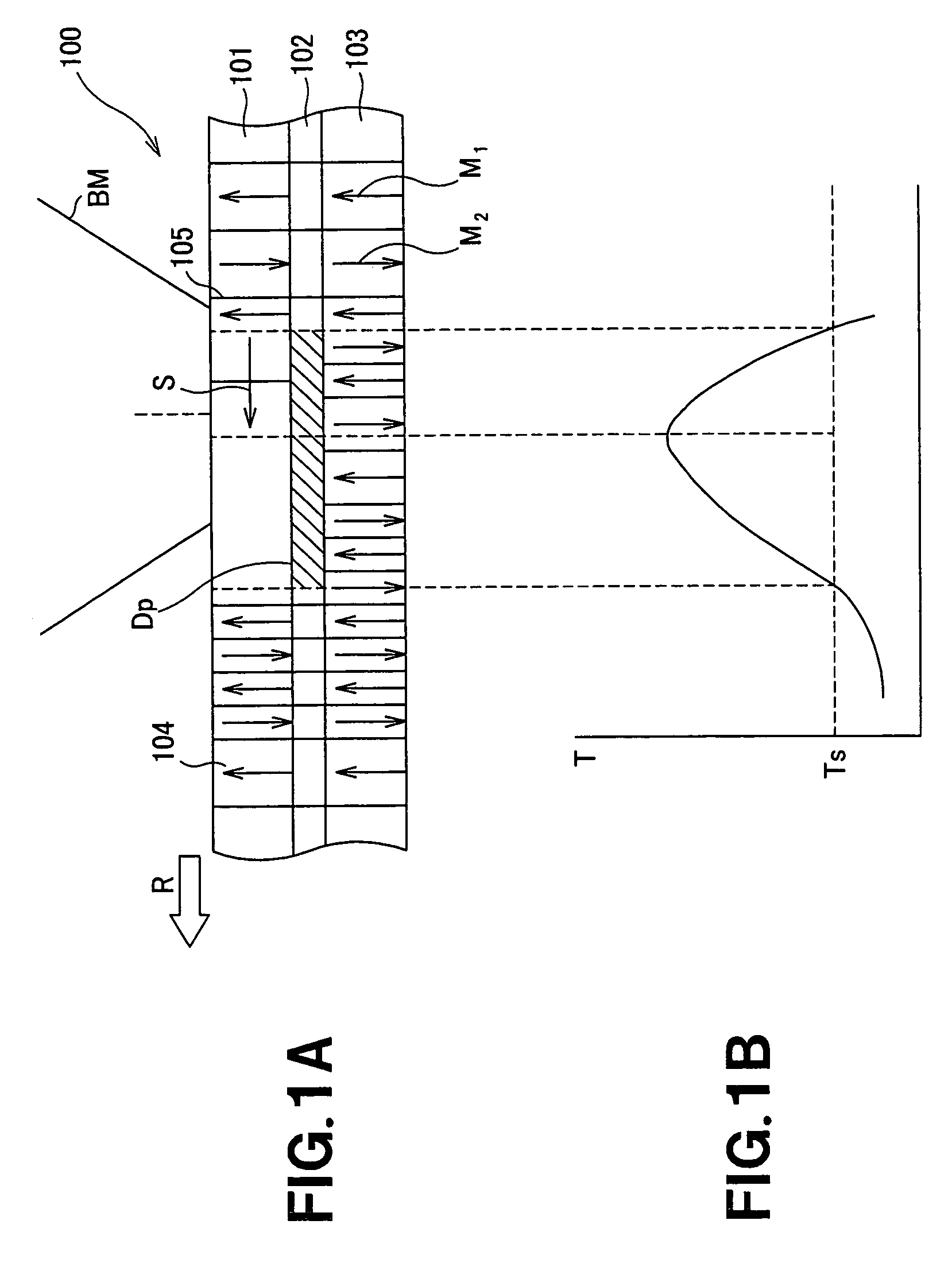
[0054]First, an application of the present invention to a magneto-optical disk adopting a so-called magnetic domain wall displacement detection (DWDD) type ultra-high resolution playback method will be explained by way of example. In this magneto-optical disk, noises from other areas than a recording track where data to be recorded and noises due to cross talk are lessened by magnetizing the land in a groove-recording type magneto-optical disk or groove in a land-recording type magneto-optical disk uniformly in a direction of canceling the influence of a fringing field from a biaxial actuator in an optical pickup head which uses an electromagnetic force as the driving force. More specifically, the above can easily be attained by magnetizing the entire surface of a magneto-optical disk uniformly in a direction opposite to the fringing field.

[0055]As abov...


PUM

PropertyMeasurementUnit
magnetic flux densityaaaaaaaaaa
frequencyaaaaaaaaaa

Abstract

A magneto-optical disk which reproduces information with an optical pickup head which uses an electromagnetic force as the driving force is provided. Other areas than at least the recording track are magnetized uniformly in a direction of canceling the influence of external magnetic field applied by the optical pickup head or a recording pattern having a frequency higher than modulation transfer function (MTF) of the optical pickup head is recorded to the other areas than at least the recording track. Read signals SP12 and SP14 from the magneto-optical disk are low in bit error rate.

Description

[0001]This application is a 371 of PCT / SP03 / 07225 Jun. 6, 2003TECHNICAL FIELD[0002]The present invention generally relates to a disk drive unit including an optical pickup head which uses an electromagnetic force as the driving force, a disk-shaped recording medium and a method of producing the recording medium, and more particularly to a disk-shaped recording medium incurring less noise from other than the recording track thereon, a method of producing the recording medium and a disk drive unit.[0003]This application claims the priority of the Japanese Patent Application No. 2002-179050 filed on Jun. 19, 2002, the entirety of which is incorporated by reference herein.BACKGROUND ART[0004]Conventionally, the magneto-optical disk is known as a rewritable disk-shaped recording medium. Recently, various techniques have been developed for improving the recording density of the magneto-optical disk. One such technique has recently been disclosed in the Japanese Unexamined Application Publ...

Claims


Application Information

Patent Timeline
Patent Type & Authority Patents(United States)
IPC IPC(8): G11B11/00G11B11/105
CPCG11B11/10523G11B11/10526G11B11/10584G11B11/10582G11B11/10532G11B11/105
Inventor TERAOKA, YOSHIYUKIWATANABE, MAKOTO
Owner SONY CORP
Why Eureka
Try Eureka