
Systems and methods for directionally drilling a borehole using a continuously variable transmission

a transmission system and directional drilling technology, applied in the direction of directional drilling, borehole/well accessories, survey, etc., can solve the problems of complex clutching or servo system, complex control system for controlling these tools, and implementation of control mechanism and torque supply of eccentric weight, etc., to achieve reliable control, low cost, and less complicated

Active Publication Date: 2007-06-26
TERRAVICI DRILLING SOLUTIONS INC
View PDF25 Cites 65 Cited by
  • Summary
  • Abstract
  • Description
  • Claims
  • Application Information

AI Technical Summary

Benefits of technology

"The present invention relates to a new drilling system controlled by mechanical continuously variable transmissions (CVTs). The system includes a CVT that is designed to vary the rotation rates of the system components based on the characteristics of the borehole being drilled. The system can be controlled by a control subsystem that can alter various parameters of the CVT, such as the transmission ratio, the effective diameter of the central cylinder, or the pitch of the conical or spherical elements. The system can also include conveyance means to move the CVT and other system components, such as wireline, coiled tubing, or a drill string. The system can be used in a rotary steerable system, a measuring-while-drilling system, or a biasing subsystem to position the system components. The technical effects of the invention include improved control of the drilling process and improved efficiency of the drilling system."

Problems solved by technology

As downhole tools for oilfield applications become more complex, the control systems for controlling these tools have also increased in complexity.
The systems themselves using direct or indirect control methods often form complicated clutching or servo-systems.
Major limitations with this design exist in the implementation of the control mechanism and the application of the torque supplied by the eccentric weight.
Therefore, the control mechanism provides only limited control of the bit shaft orientation.
The system becomes unstable when the torque required to orient the bit shaft is greater than that which can be supplied by the eccentric weight.
However, they are only today beginning to see widespread use as a fuel-saving technology in the automotive industry.
However, CVTs that use belts (or sometimes chains) are limited to fairly light vehicles, usually those weighing under about 2,000 pounds.

Method used


Image

  • Systems and methods for directionally drilling a borehole using a continuously variable transmission
  • Systems and methods for directionally drilling a borehole using a continuously variable transmission
  • Systems and methods for directionally drilling a borehole using a continuously variable transmission

Examples


Embodiment Construction

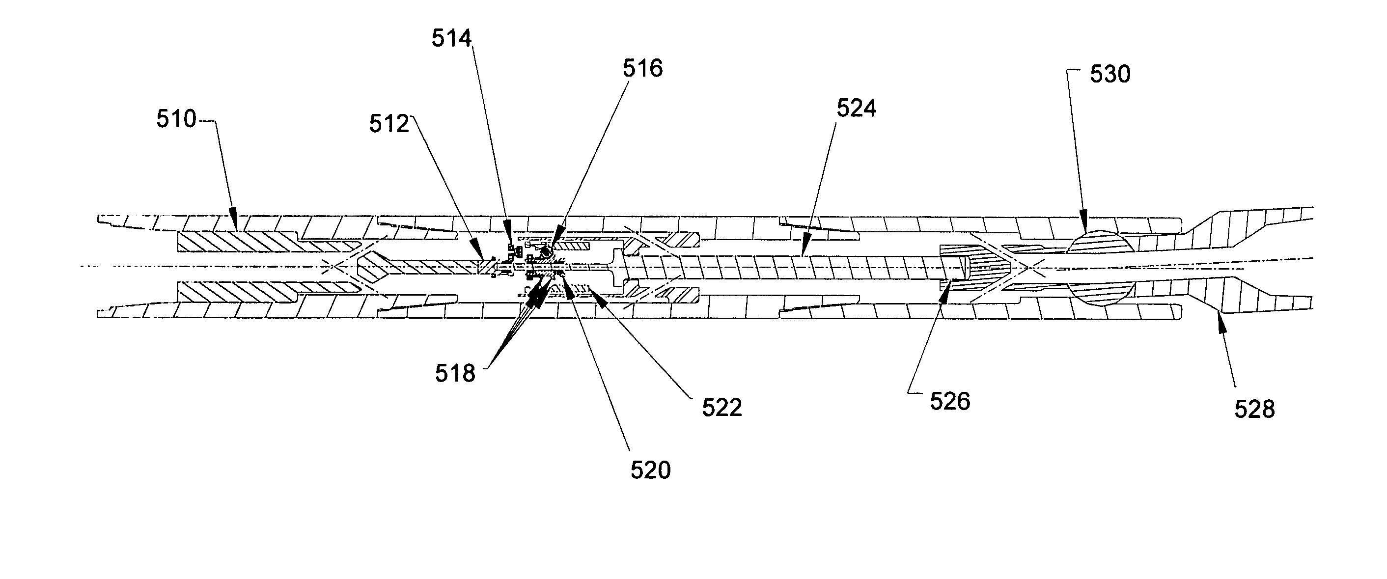
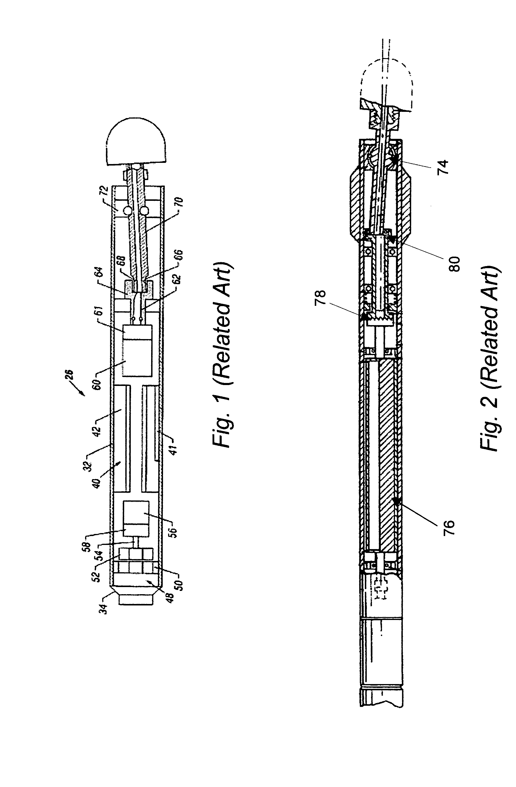
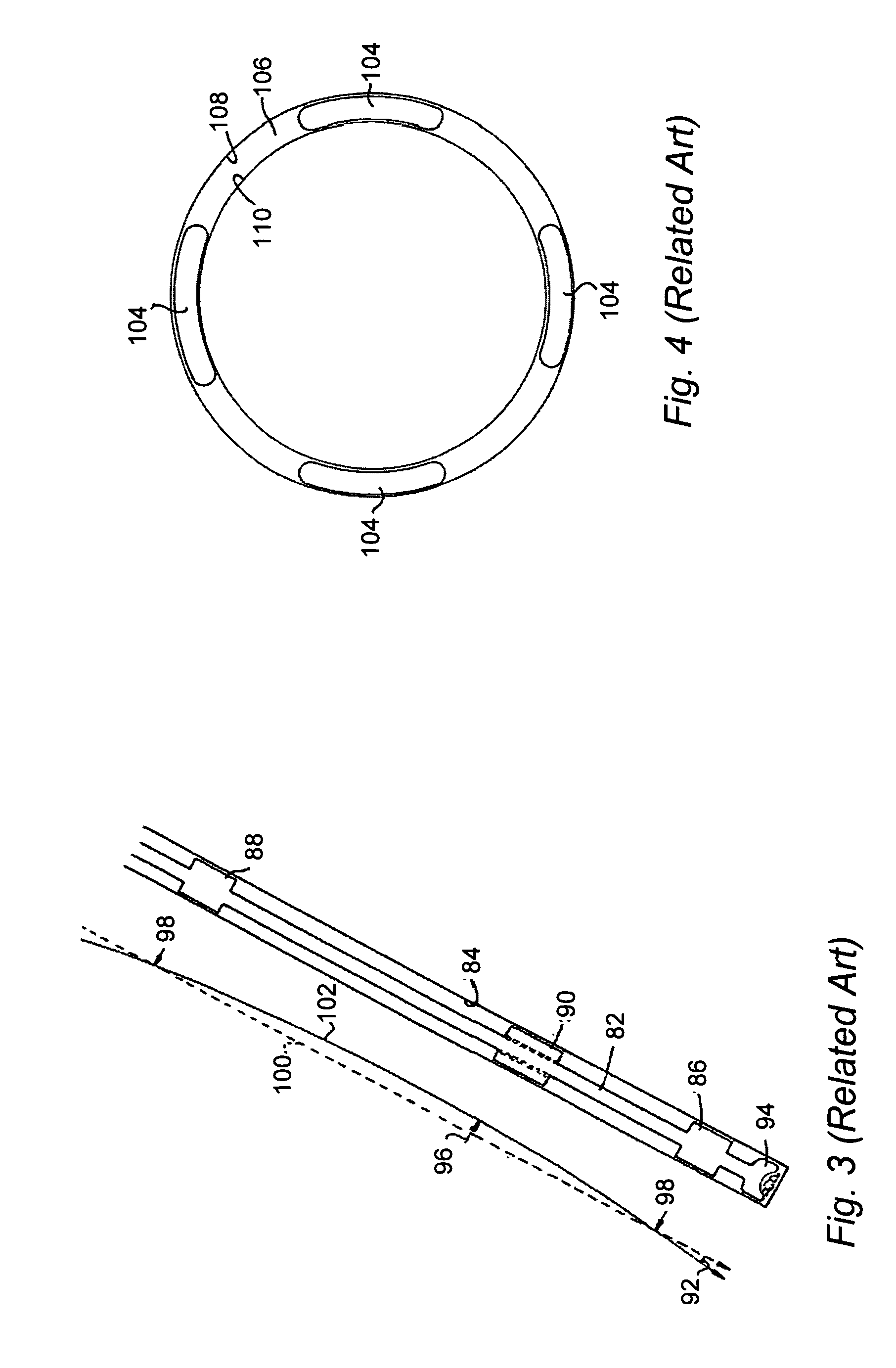
[0115]Turning now to the drawings, it is noted that FIGS. 11–35 (as well as FIGS. 1–10 described above) are not drawn to scale. In particular, the scale of some of the elements of the figures is greatly exaggerated to emphasize characteristics of the elements. It is also noted that FIGS. 1–35 are not drawn to the same scale.

[0116]The following description generally relates to systems and methods that use continuously variable transmissions (CVTs) to control one or more components. For example, a system configured for drilling a borehole and / or completing a well may include a CVT. An input shaft of the CVT is coupled to a power supply, and an output shaft of the CVT is coupled to one or more system components such that the CVT controls the one or more system components. The one or more system components may include, but are not limited to, a bottom hole assembly, a bit shaft, another component coupled to the bottom hole assembly, one or more components of a biasing subsystem, one or ...


PUM


Abstract

Systems and methods for directionally drilling a borehole are provided. One system includes a biasing subsystem that is configured to control a tendency of a bottom hole assembly during drilling of the borehole. The system also includes a continuously variable transmission. An output shaft of the continuously variable transmission is coupled to the biasing subsystem such that the continuously variable transmission is configured to control relative rotation of one or more components of the biasing subsystem during the drilling. One method includes controlling a tendency of a bottom hole assembly during drilling of the borehole using a biasing subsystem. The method also includes controlling relative rotation of one or more components of the biasing subsystem using a continuously variable transmission during the drilling. The one or more components are coupled to an output shaft of the continuously variable transmission.

Description

PRIORITY CLAIM[0001]This application claims priority to U.S. Provisional Application No. 60 / 465,395 entitled “Rotary Steerable Device Utilizing Continuously Variable Transmissions for Use in Drilling Applications,” filed Apr. 25, 2003.BACKGROUND OF THE INVENTION[0002]1. Field of the Invention[0003]This invention generally relates to systems and methods for directionally drilling a borehole. Certain embodiments relate to a system for directionally drilling a borehole that includes a continuously variable transmission that is configured to control relative rotation of one or more components of a biasing subsystem during drilling of the borehole.[0004]2. Description of the Related Art[0005]The following descriptions and examples are not admitted to be prior art by virtue of their inclusion within this section.[0006]As downhole tools for oilfield applications become more complex, the control systems for controlling these tools have also increased in complexity. Many downhole tools attem...

Claims


Application Information

Patent Timeline
Patent Type & Authority Patents(United States)
IPC IPC(8): E21B7/04E21B3/02E21B4/00E21B43/12E21B47/18
CPCE21B3/02E21B4/006E21B7/04E21B43/12E21B47/18Y10T74/1505F16H15/20F16H15/38F16H15/40
Inventor SCHAAF, STUART
Owner TERRAVICI DRILLING SOLUTIONS INC
Learn More