Tailgate structure for receiving supplemental tailgate

Active Publication Date: 2007-06-26
FORD GLOBAL TECH LLC
View PDF16 Cites 33 Cited by
  • Summary
  • Abstract
  • Description
  • Claims
  • Application Information

AI Technical Summary

Benefits of technology

[0018]It is still another advantage of this invention that a mounting bracket for supporting a grab handle mechanism may be incorporated into the internal modifications around a guide tube to provide support for the deployment of a grab handle to be utilized in conjunction with deployment of the supplemental tailgate apparatus when being utilized as a step function.
[0019]It is a further advantage of this invention that the mounting bracket for detachably connecting the guide tube to the C-channel can be welded directly to the guide tube.
[0020]It is another object of this invention to provide a main tailgate assembly that will permit the receipt of and deployment of a supplemental tailgate apparatus from the interior of a main tailgate assembly while maintaining the conventional appearance of the main tailgate assembly for a pick-up truck.
[0021]It is still another object of this invention to support in a rigid manner a supplemental tailgate apparatus within the interior of a main tailgate assembly without incurring rattles resulting from an interfering supplemental tailgate apparatus.
[0022]It is a further object of this invention to provide a main tailgate assembly for use with a supplemental tailgate apparatus that i

Problems solved by technology

Some of the bed extenders mount to the outside of the tailgate or to the box itself, which may be convenient for deployment, but they tend to interfere with cargo space in the box since the bed extender, when not in use, protrudes into the box.
Moreover, it is typical for the vehicle operator to employ the extender only occasionally, so it is generally undesirable to have the extender exposed at all times, which detracts from the attractiveness of the vehicle.
Again, though, typical box extenders that provide adequate functionality are externally mounted and not only detract from the vehicle appearance when not in use but also require chang

Method used


Image

  • Tailgate structure for receiving supplemental tailgate
  • Tailgate structure for receiving supplemental tailgate
  • Tailgate structure for receiving supplemental tailgate

Examples


Example

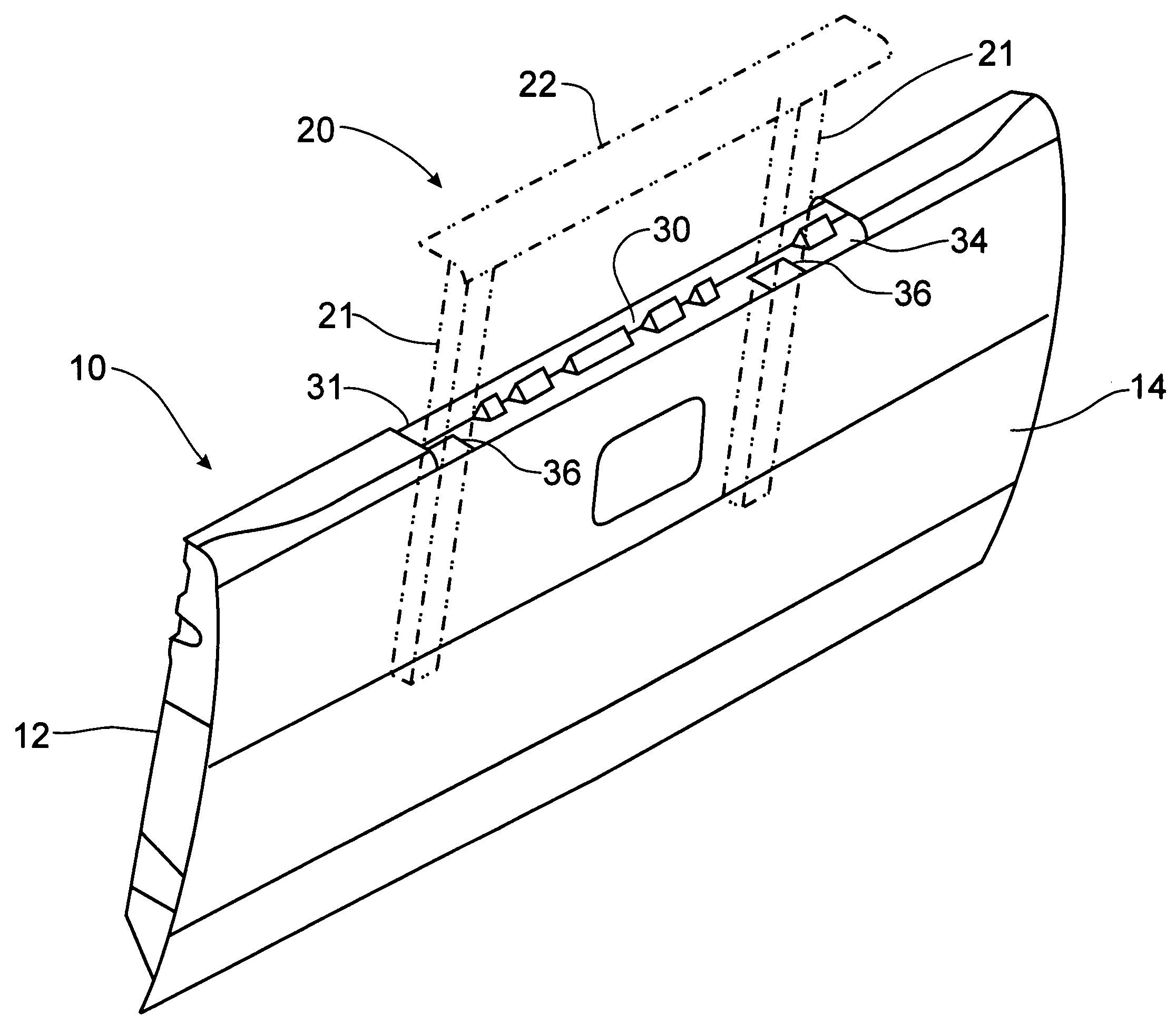
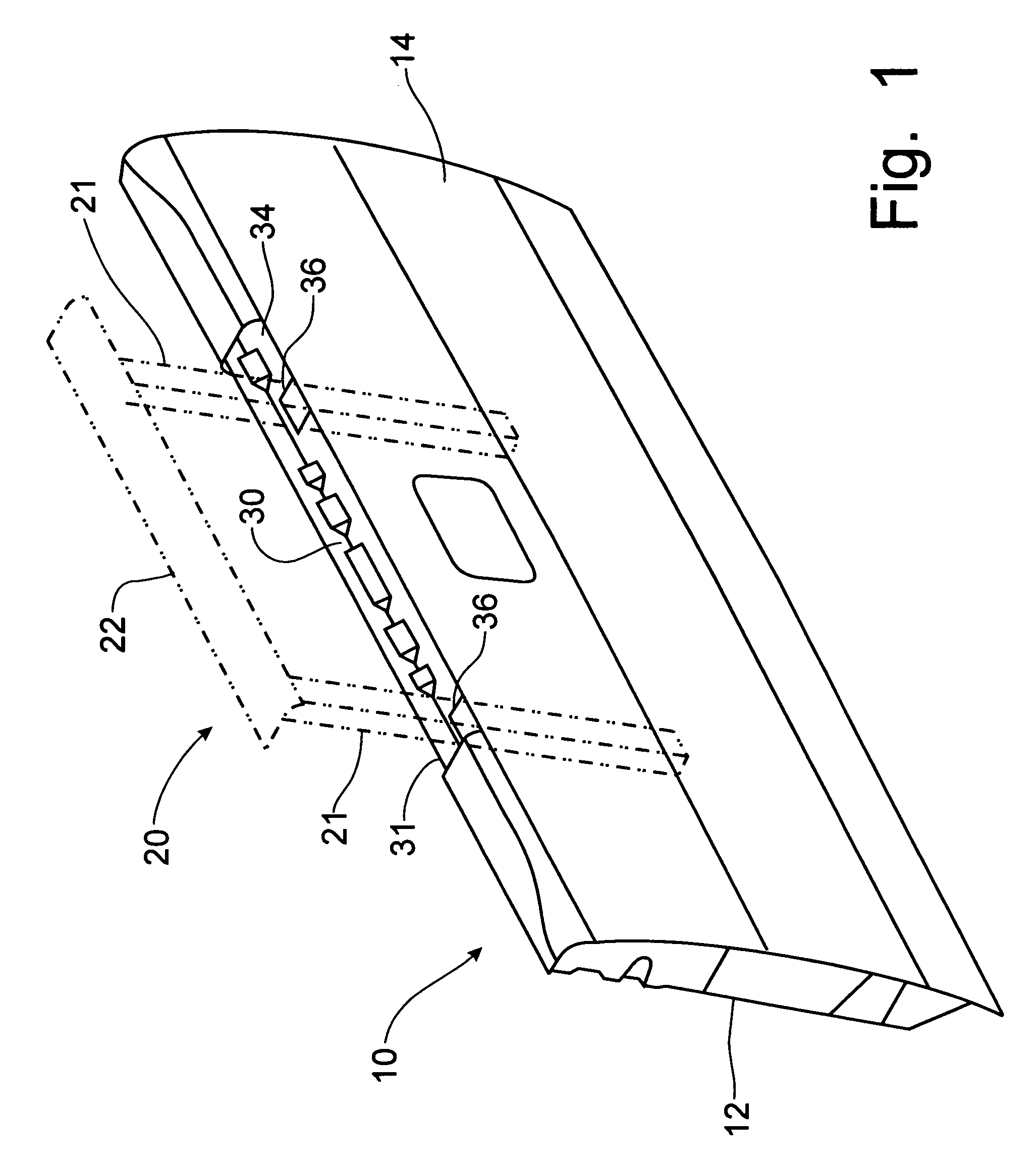
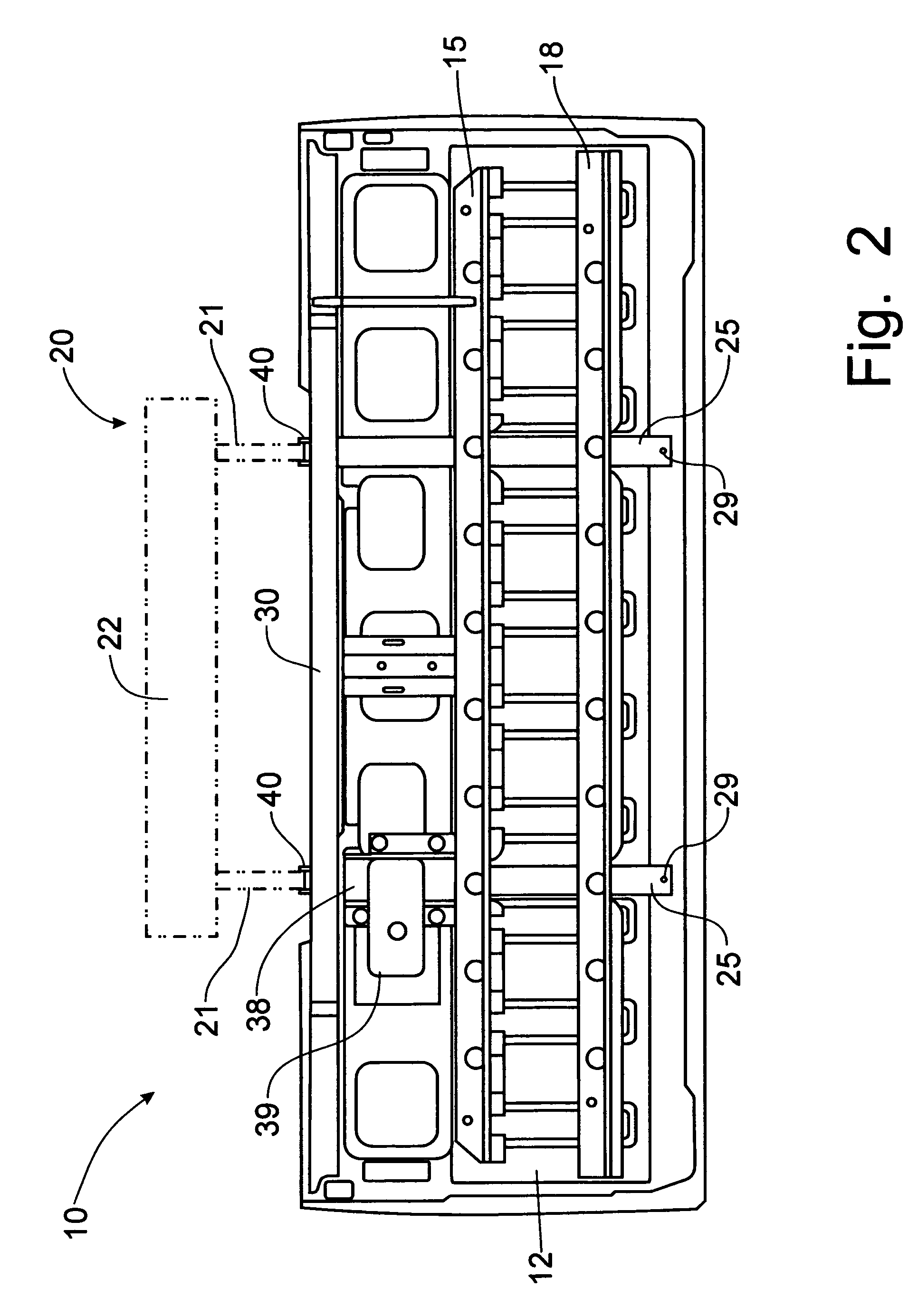
[0036]Referring to FIGS. 1-4, a tailgate assembly for pivotally mounting on a pick-up truck cargo bed incorporates the principles of the instant invention. Any left and right references are used as a matter of convenience and are determined by standing at the rear of the cargo bed where the tailgate is pivotally mounted and facing the cargo bed, the normal direction of travel of the pick-up truck. The tailgate assembly 10 is configured for the mounting of a supplemental tailgate apparatus 20 of the type disclosed in U.S. Pat. No. 6,918,624, granted on Jul. 19, 2005, to Scott Miller, et al, the contents of which are incorporated herein by reference in its entirety. Furthermore, the supplemental tailgate apparatus 20 can have associated therewith an optional grab handle device (not shown), which is disclosed in U.S. patent application Ser. No. 11 / 236,133, of Steve Bruford, et al, entitled “Grab Handle for Use with Supplemental Tailgate on Pick-Up Trucks”, now U.S. Pat. No. 7,090,276, ...


PUM


Abstract

A tailgate structural configuration accommodates the housing of a supplemental tailgate internally within the tailgate. The tailgate is formed with an outer panel and an inner panel to define an internal cavity. The upper portion of the tailgate includes a C-channel frame member connected to both the inner and outer panels to support guide tubes telescopically housing the supplemental tailgate. To enhance structural stability, the tailgate further includes one or two transversely oriented strainers having formed therein flanged depressions or openings for the passage of the guide tubes vertically therethrough. Each guide tube is affixed to a mounting bracket that is detachably connected to the C-channel to support the guide tube within the tailgate. Positioning pins mounted on the mounting bracket affixed to the guide tubes engage locator holes in the C-channel for positioning the supplemental tailgate.

Description

CROSS-REFERENCE TO RELATED APPLICATIONS[0001]This application claims domestic priority on U.S. Provisional Patent Application Ser. No. 60 / 743,277, filed on Feb. 10, 2006, and entitled “Modified Tailgate to House a Supplemental Tailgate”, the contents of which are incorporated herein by reference.FIELD OF THE INVENTION[0002]This invention relates to the utilization of a supplemental tailgate apparatus housed with the tailgate of a pick-up truck and, more particularly, to structural modifications made to the tailgate assembly to receive a supplemental tailgate apparatus for deployment therefrom.BACKGROUND OF THE INVENTION[0003]Conventionally, pickup trucks include a tailgate at the back of a bed that closes off a cargo box. Often times, the truck bed is not long enough to hold the cargo, so truck bed extenders have been developed. The truck bed extenders work in conjunction with the open tailgate in order to provide additional length to the bed. Some of the bed extenders mount to the ...

Claims


Application Information

Patent Timeline
IPC IPC(8): B62D25/00
CPCB62D33/0273
Inventor FIRZLAFF, JEFFKOEHLER, DUANETAN, KIAN-HUAT
Owner FORD GLOBAL TECH LLC
Why Eureka
Try Eureka