Load driving device and portable apparatus utilizing such driving device

a technology of driving device and driving device, which is applied in the direction of electric variable regulation, process and machine control, instruments, etc., can solve the disadvantages of disadvantageous overall efficiency of electronic devices including increase energy loss, and require additional space and cost for power supply circuits and loads

Active Publication Date: 2007-06-26
ROHM CO LTD
View PDF13 Cites 39 Cited by
  • Summary
  • Abstract
  • Description
  • Claims
  • Application Information

AI Technical Summary

Benefits of technology

[0007]It is, therefore, an object of the invention to provide a load driving device having a dc-dc conversion type power supply circuit for generating an output voltage by converting a power supply voltage (an input voltage), the power supply circuit capable of adjusting the magnitude of the load current within a predetermined range while avoiding the energy loss caused by an increase in the load current, thereby enabling efficient driving of the load.
[0014]As described above, the voltage drop across a constant-current source is controlled automatically to become equal to the reference voltage so that the current is maintained at the preset magnitude. Therefore, even if the currents flowing through the LEDs grow larger, there will be no such energy loss as would be incurred by a voltage detecting resistor. Thus, substantially no extra energy loss is caused by an increase in the load current that the load driving device of the invention can efficiently drive a load over a wide range of load current.
[0015]An adjustable-current type constant-current source can be provided for each load consisting of a set of LEDs in such a way that the dc-dc conversion type power supply circuit is controlled based on the lowest one of the voltage drops across the constant-current sources. This ensures stable supply of a predetermined constant current to each of the LEDs constituting the load.
[0022]For a constant-current load, such as a set of LEDs, having an operating point that depends on the magnitude of the current flowing through it, an adjustable-current type constant-current source may be connected in series with the load. It is thus possible to provide the load with a required magnitude of current in a stable manner.
[0024]Moreover, when the output voltage tends to drop below the predetermined voltage due to the adjustment of current for the LEDs, the output voltage may be controlled to remain at the predetermined voltage. Thus, it is possible to secure the predetermined output voltage for the non-constant-current type load.

Problems solved by technology

In such a case as mentioned above, the voltage detection resistor connected in series with the load will increase energy loss when the load current is increased.
Therefore, the overall efficiency of the electronic device that includes a power supply circuit and a load disadvantageously drops when the load current becomes large (i.e. during a heavy duty).
In such case, conventionally it is necessary to provide a further appropriate power supply circuit to meet individual use conditions, which requires additional space and cost for the power supply circuit and load.

Method used


Image

  • Load driving device and portable apparatus utilizing such driving device
  • Load driving device and portable apparatus utilizing such driving device
  • Load driving device and portable apparatus utilizing such driving device

Examples


second embodiment

[0050]FIG. 5 shows a circuit structure of a load driving device in accordance with the invention. As shown in FIG. 5, the load driving device has a further load 20 in addition to the forgoing load 10. Furthermore, a constant-current source I20 is provided in association with the load 20. It should be understood that more than two loads can be added.

[0051]In the arrangement shown in FIG. 5, a constant-current source I10 is connected in series with the load 10, through which flows a drive current Io1. The voltage drop across the constant-current source I10 is utilized as a first detection voltage Vdet1. Similarly, a constant-current source I20 is connected in series with the load 20, through which flows a drive current Io2. The voltage drop across the constant-current source I20 is used as the second detection voltage Vdet2. Symbols P11, P12, P21, and P22 indicate terminals for connection with the loads.

first embodiment

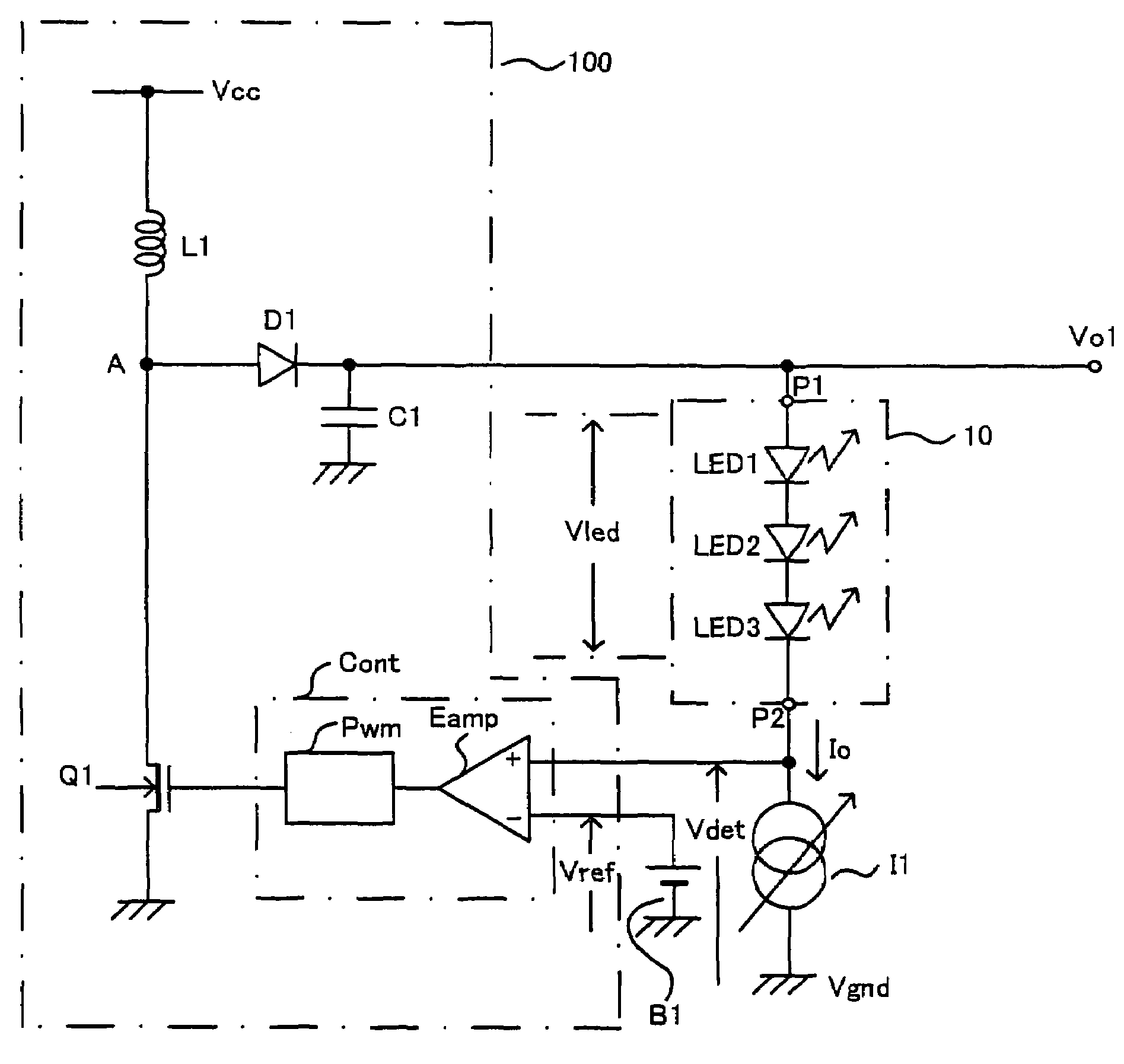
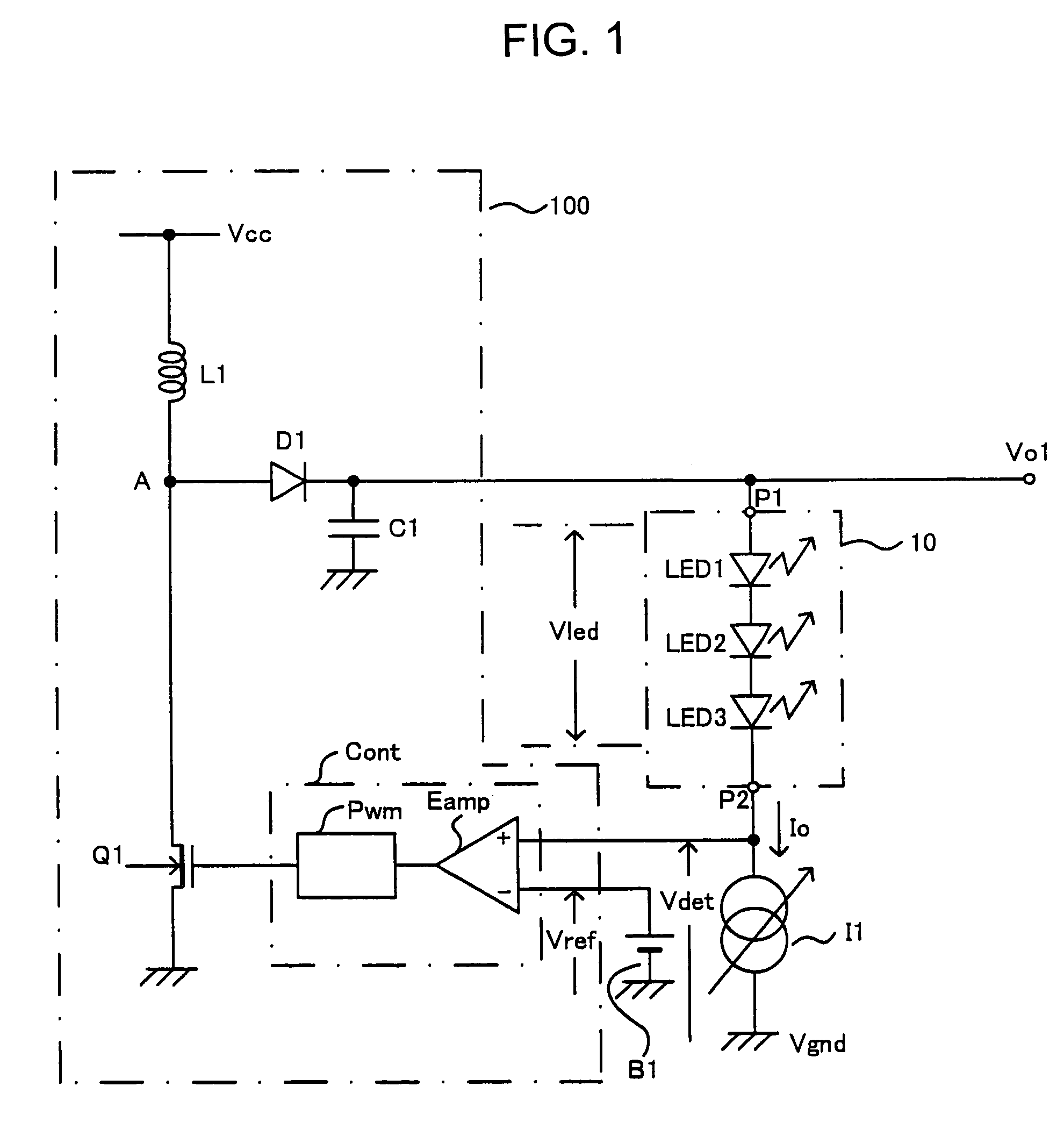
[0052]An error amplifier Eamp of the control circuit Cont has two non-inverting input terminals (+) and one inverting input terminal (−). The two non-inverting input terminals (+) are fed with a first detection voltage Vdet1 and a second detection voltage Vdet2, one for each terminal, while the inverting input terminal (−) is fed with the reference voltage Vref. In the error amplifier Eamp, the lower one of the first detection voltage Vdet1 and the second detection voltage Vdet2 is compared with the reference voltage Vref. Rest of the circuit structure is the same as that of the first embodiment shown in FIG. 1.

[0053]The load driving device of FIG. 5 can adjust the individual drive currents Io1 and Io2 independently. The lower one of the voltage drops Vdet1 and Vdet2 of the constant-current sources I10 and I20, respectively, is automatically selected in the controlled switching operation performed by the power supply circuit 100, thereby securing operations of the constant-current s...

third embodiment

[0055]FIG. 6 shows a circuit structure of a load driving device in accordance with the invention. As seen in FIG. 6, the switching power supply circuit 100 has the same configuration as the one shown in FIG. 1.

[0056]In the third embodiment, connected in series between a node providing an output voltage Vo and the ground are a first external load (referred to as first load) 10 driven by a predetermined constant current, a variable-resistance means in the form of N-type transistor Q2 having variable resistance in response to a control signal, and a resistor R1 serving as a current detection means. The first load 10 is a load having an operating point that depends on the magnitude of the current flowing through it. In this example, the load 10 is provided with the drive current Io of a predetermined magnitude. The voltage drop across the resistor R1 is used as the first detection voltage Vdet1.

[0057]The control circuit Cont is fed with the first detection voltage Vdet1 along with a fir...


PUM


Abstract

A load such as an LED and a constant-current source are connected in series with each other between the node of a dc-dc conversion type power supply circuit providing an output voltage and the ground. The constant-current source provides a constant current Io, the magnitude of which can be adjusted. The power supply circuit controls the output voltage such that the voltage drop across the constant-current source serving as a detection voltage becomes equal to a reference voltage. Thus, the load current can be varied within a predetermined range while avoiding the power loss due to an increase in the load current, thereby always permitting efficient operation of the load.

Description

FIELD OF THE INVENTION[0001]This invention relates to a device for driving a load (load driving device) with the output voltage by converting an inputted power supply voltage by means of a dc-dc conversion type power source circuit, and to a portable apparatus equipped with such load driving device.BACKGROUND OF THE INVENTION[0002]There have been many devices in use for driving loads such as LEDs, utilizing a dc-dc conversion type power supply circuit adapted to provide an output voltage different from an inputted power supply voltage. A typical load driving device has a power supply circuit that generates a predetermined output voltage and an output current for driving a load, as disclosed in Japanese Patent Application Laid Open No. 2001-313423. For this purpose, the level of the output voltage or the output current supplied to the load is measured to establish a detection voltage or detection current, which is fed back to a control circuit of the power supply circuit.[0003]In suc...

Claims


Application Information

Patent Timeline
Patent Type & Authority Patents(United States)
IPC IPC(8): G05F1/10H01S3/00H05B37/00H02H7/10H02M3/155H05B44/00
CPCH05B33/0815H05B33/0827Y02B20/347H05B45/46Y02B20/30H05B45/38H05B45/10H05B45/397H05B45/34H02M3/155
Inventor MURAKAMI, SADAKAZU
Owner ROHM CO LTD
Why Eureka
Try Eureka