Coupled multi-band antenna

a multi-band antenna and coupling technology, applied in the direction of resonant antennas, antenna earthings, radiating element structural forms, etc., can solve the problems of antennas, insufficient bandwidths in both high and low frequencies, and the first difficulty in overcoming antennas, so as to achieve good multi-band operation, smooth impedance variation, and large bandwidth

Active Publication Date: 2007-06-26
ADVANCED WIRELESS
View PDF3 Cites 20 Cited by
  • Summary
  • Abstract
  • Description
  • Claims
  • Application Information

AI Technical Summary

Benefits of technology

[0014]The above-mentioned objectives are implemented using the following technical features. The primary structure of the disclosed multi-band antenna includes a coupled radiator, a feed wire, a first radiating extension, and a second radiating extension. The coupled radiator is the primary radiator of the antenna that can operate at multiple bands. It has a microwave substrate, a coupled metal element, a first radiating element, a second radiating element, and a connecting portion. The coupled metal element is disposed on a surface of the microwave substrate, and connected to the positive signal wire of the feed wire. The first radiating element is also disposed on a surface of the microwave substrate, in the vicinity of the coupled metal element to form a coupled structure with a gap less than or equal to 3 mm. The second radiating element is disposed on a surface of the microwave substrate, and connected to the negative signal wire of the feed wire. Its extension direction is roughly parallel to the first radiating element. The connecting portion is disposed on a surface of the microwave substrate for an electrical connection between the first and second radia...

Problems solved by technology

However, such varieties cause troubles and inconvenience for both system suppliers and consumers.
However, the first difficulty to overcome is the antenna.
The distance between the first conductive plate A1 and the second conductive plate B1 is too short, result...

Method used


Image

  • Coupled multi-band antenna
  • Coupled multi-band antenna
  • Coupled multi-band antenna

Examples


first embodiment

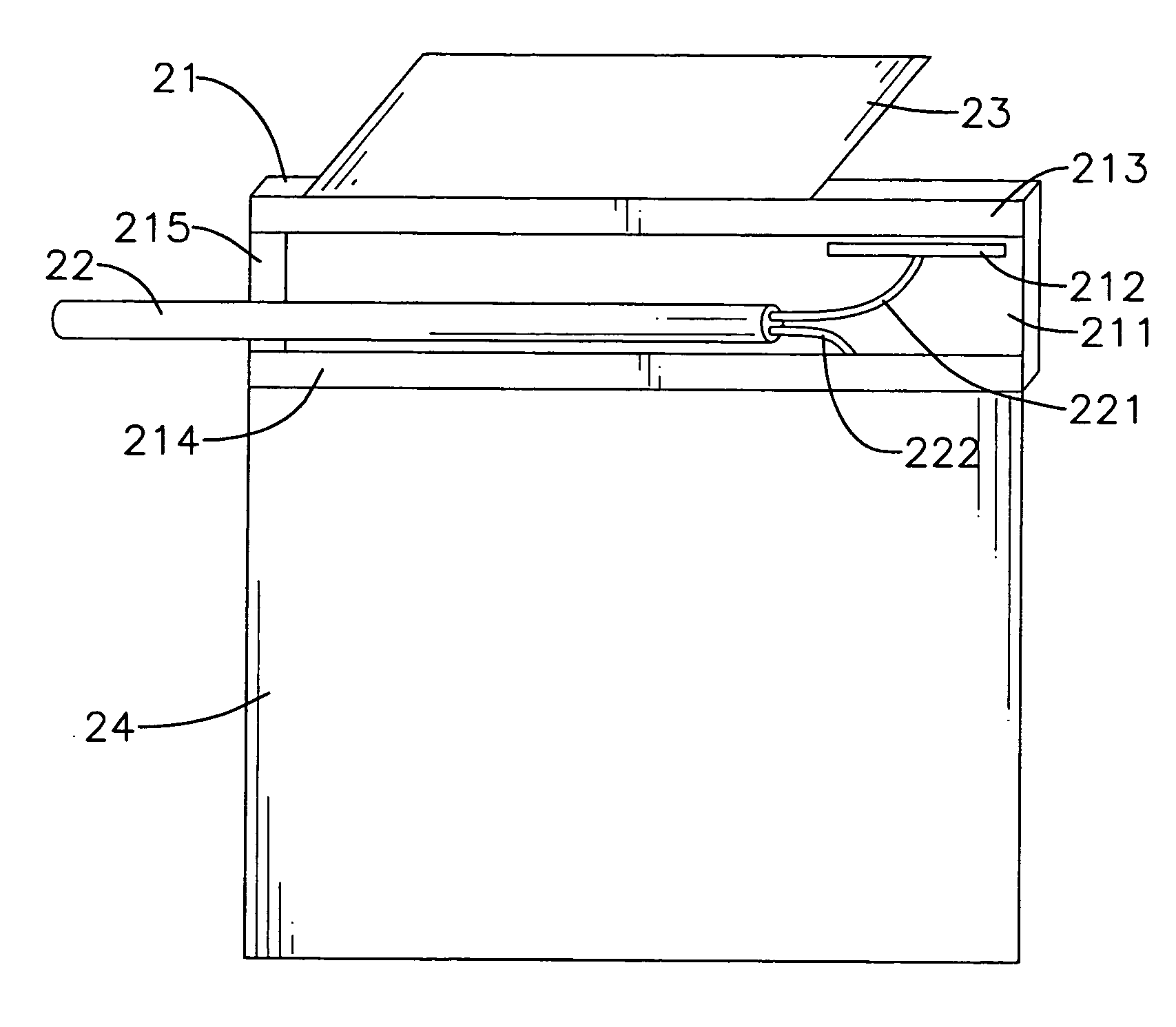
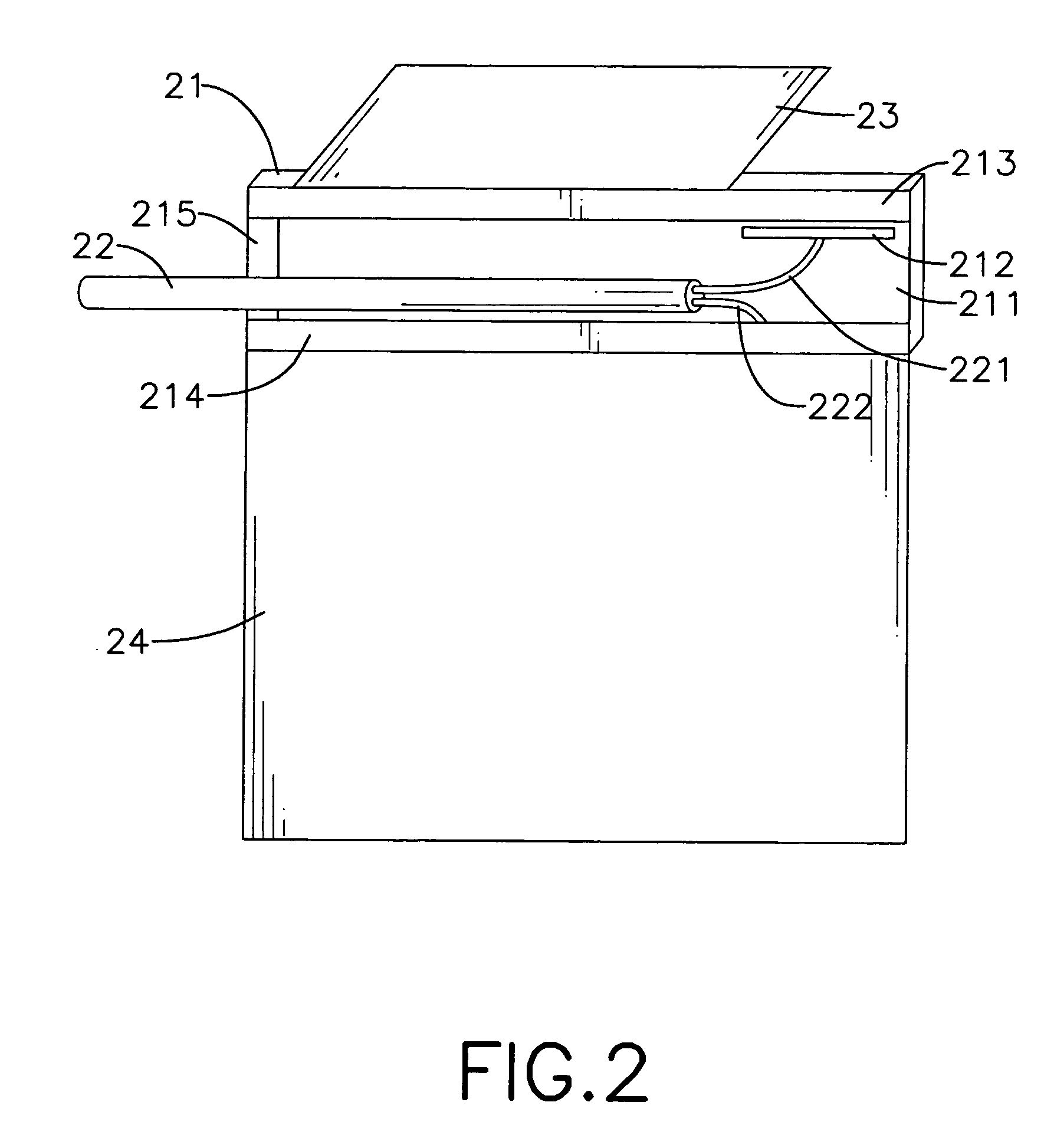
[0021]the coupled multi-band antenna is shown in FIG. 2. The antenna includes a coupled radiator 21, a feed wire 22, a first radiating extension 23, and a second radiating extension 24. The coupled radiator 21 has a microwave substrate 211, a coupled metal element 212, a first radiating element 213, a second radiating element 214, and a connecting portion 215. The coupled metal element 212 is disposed on one surface of the microwave substrate 211. The first radiating element 213 is disposed on one surface of the microwave substrate 211 and in the vicinity of the coupled metal element 212 to form a coupled structure with a gap less than or equal to 3 mm. The second radiating element 214 is disposed on one surface of the microwave substrate 211, and its extension direction is roughly parallel to the first radiating element 213. The connecting portion 215 is disposed on one surface of the microwave substrate 211, and its both ends are connected respectively to the first radiating eleme...

second embodiment

[0023]the disclosed coupled multi-band antenna is shown in FIG. 4. It includes a coupled radiator 41, a feed wire 42, a first radiating extension 43, and a second radiating extension 44. The coupled radiator 41 has a microwave substrate 411, a coupled metal element 412, a first radiating element 413, a second radiating element 414, and a connecting portion 415. The coupled metal element 412 is disposed on one surface of the microwave substrate 411. The first radiating element 413 is disposed on one surface of the microwave substrate 411 and in the vicinity of the coupled metal element 412 to form a coupled structure with a minimal gap less than 3 mm. The second radiating element 414 is disposed on one surface of the microwave substrate 411, and its extension direction is roughly parallel to the first radiating element 413. The connecting portion 415 is disposed on one surface of the microwave substrate 411, and its both ends are connected respectively to the first radiating element ...

third embodiment

[0024]the disclosed coupled multi-band antenna is shown in FIG. 5. It includes a coupled radiator 51, a feed wire 52, a first radiating extension 53, and a second radiating extension 54. The coupled radiator 51 has a microwave substrate 511, a coupled metal element 512, a first radiating element 513, a second radiating element 514, and a connecting portion 515. The coupled metal element 512 is disposed on one surface of the microwave substrate 511. The first radiating element 513 is disposed on one surface of the microwave substrate 511 and in the vicinity of the coupled metal element 512 to form a coupled structure with a gap less than or equal to 3 mm. The second radiating element 514 is disposed on one surface of the microwave substrate 511, and its extension direction is roughly parallel to the first radiating element 513. The connecting portion 515 is disposed on one surface of the microwave substrate 511, and its both ends are connected respectively to the first radiating elem...


PUM


Abstract

A coupled multi-band antenna with the broadband function includes a coupled radiator, a feed wire, a first radiating extension, and a second radiating extension. The coupled radiator has a microwave substrate, a coupled metal element, a first radiating element, a second radiating element, and a connecting portion. The coupled metal element is connected to the positive terminal of the feed wire, and the second radiating element is connected to the negative terminal of the feed wire for the purposes of transmitting electrical signals and generating the multi-band operating modes of the antenna. By connecting the first and second radiating extensions to the coupled radiator, the surface current distribution and impedance variation of the antenna can be effectively adjusted to provide multi-band functions. The antenna utilizes the simple structure of coupled radiator to achieve multi-band operations and uses the radiating extensions to provide sufficient bandwidths.

Description

BACKGROUND OF THE INVENTION[0001]1. Field of the Invention[0002]The invention relates to a coupled multi-band antenna and, in particular, to a multi-band antenna with the broadband function.[0003]2. Description of Related Art[0004]Personal mobile communications have proved its great potential and business opportunities in radio communication industry. During its evolution process, many systems have been developed, using different technologies and channels. They also play important roles in different areas and markets. However, such varieties cause troubles and inconvenience for both system suppliers and consumers. One crucial point is that different systems use different frequency bands (e.g., GSM900, PCS1900, and UMTS).[0005]In order for users to operate with greater ease, the industry has invested a lot of manpower to develop products with multi-band integrations. However, the first difficulty to overcome is the antenna. One may say that the antenna is both the beginning and end o...

Claims


Application Information

Patent Timeline
IPC IPC(8): H01Q1/24
CPCH01Q1/243H01Q5/30H01Q9/0457H01Q9/0421
Inventor LIN, SHENG-CHIHCHIU, TSUNG-WENHSIAO, FU-REN
Owner ADVANCED WIRELESS
Why Eureka
Try Eureka