
Systems and apparatus for integrated X-Ray tube cooling

a technology of cooling system and x-ray tube, which is applied in the cooling of x-ray tube, x-ray tube, x-ray tube vessel, etc., can solve the problems of low power density solution, mass and geometry inefficient, and enormous heat generated by x-ray tub

Active Publication Date: 2007-06-26
GENERAL ELECTRIC CO
View PDF2 Cites 20 Cited by
  • Summary
  • Abstract
  • Description
  • Claims
  • Application Information

AI Technical Summary

Benefits of technology

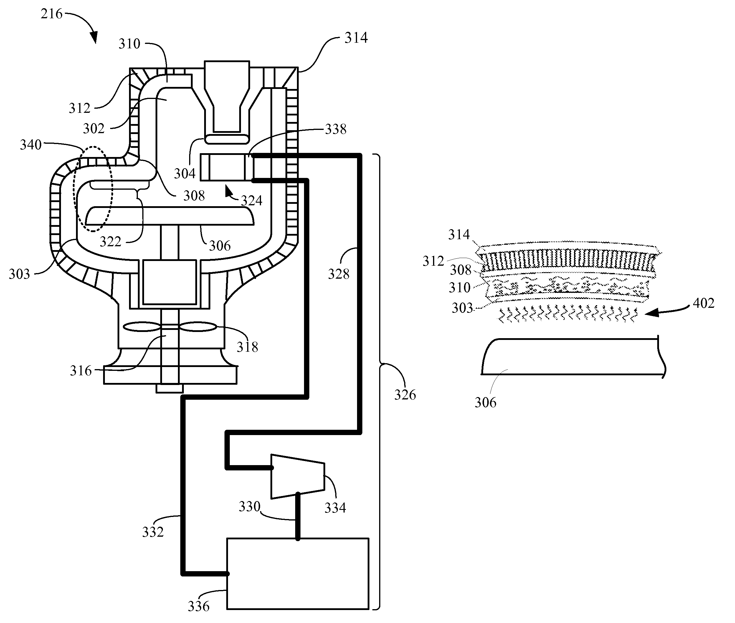
[0010]An X-Ray tube is provided. The X-Ray tube includes a frame structure surrounding at least a portion of an electron beam source and an electron beam target. The frame structure has a cooling system integrated therein. The cooling system includes an air / fin layer; and a sub-cooled working fluid in thermal contact with the air / fin layer, the sub-cooled working fluid being adapted to undergo a phase change in response to heat introduced to the frame structure by one or more of the electron beam source and the electron beam target, wherein the phase change facilitates transfer of the heat to the at least one air / fin layer.
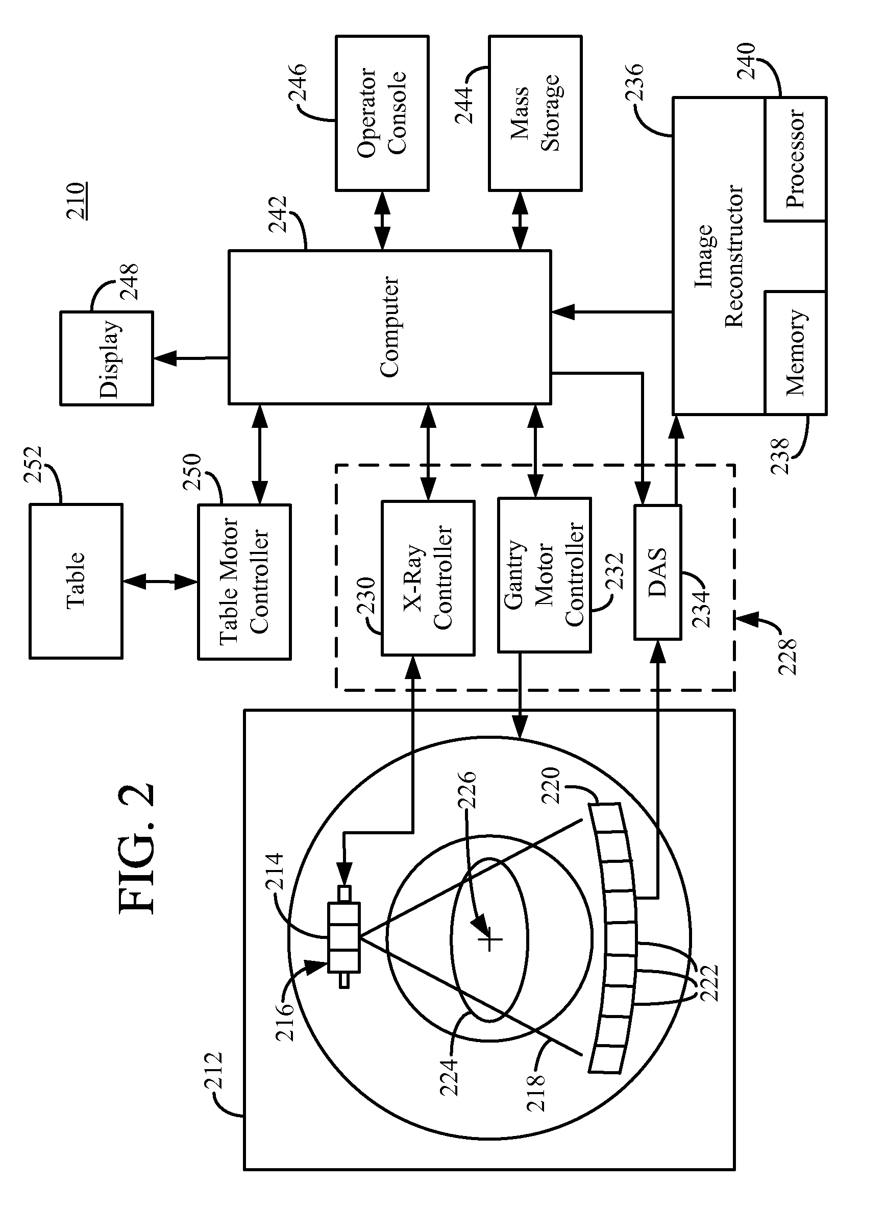
[0012]A computed tomography (CT) imaging system is also provided. The CT imaging system has a gantry with an array of X-Ray detectors mounted opposite an X-Ray tube. The X-Ray tube includes a frame structure surrounding at least a portion of an electron beam source and an electron beam target. The frame structure includes a cooling system integrated therein. The cooling system includes an air / fin layer; and a sub-cooled working fluid in thermal contact with the air / fin layer, the sub-cooled working fluid being adapted to undergo a phase change in response to heat introduced to the frame structure by one or more of the electron beam source and the electron beam target, wherein the phase change facilitates transfer of the heat to the at least one air / fin layer.

Problems solved by technology

The generation of the X-Ray beam by the X-Ray tube creates enormous amounts of heat, especially in the areas surrounding the electron beam target.
This low power density solution is mass and geometry inefficient.
This can be difficult and uncomfortable.
These higher heat levels, however, can reach, or exceed, the capacity of current cooling systems.

Method used


Image

  • Systems and apparatus for integrated X-Ray tube cooling
  • Systems and apparatus for integrated X-Ray tube cooling
  • Systems and apparatus for integrated X-Ray tube cooling

Examples


Embodiment Construction

[0018]Accordingly, an X-Ray tube 216 is provided having an integrated cooling system. The integrated cooling system couples efficient heat transfer, via a sub-cooled high temperature nucleate boiling working fluid, and circulated (forced) air cooling. The integrated cooling system enhances heat transfer rates and efficiency, allowing for higher power, and thus higher heat-producing, applications. Further, the dependence on large, space-consuming conventional, remote cooling systems is eliminated.

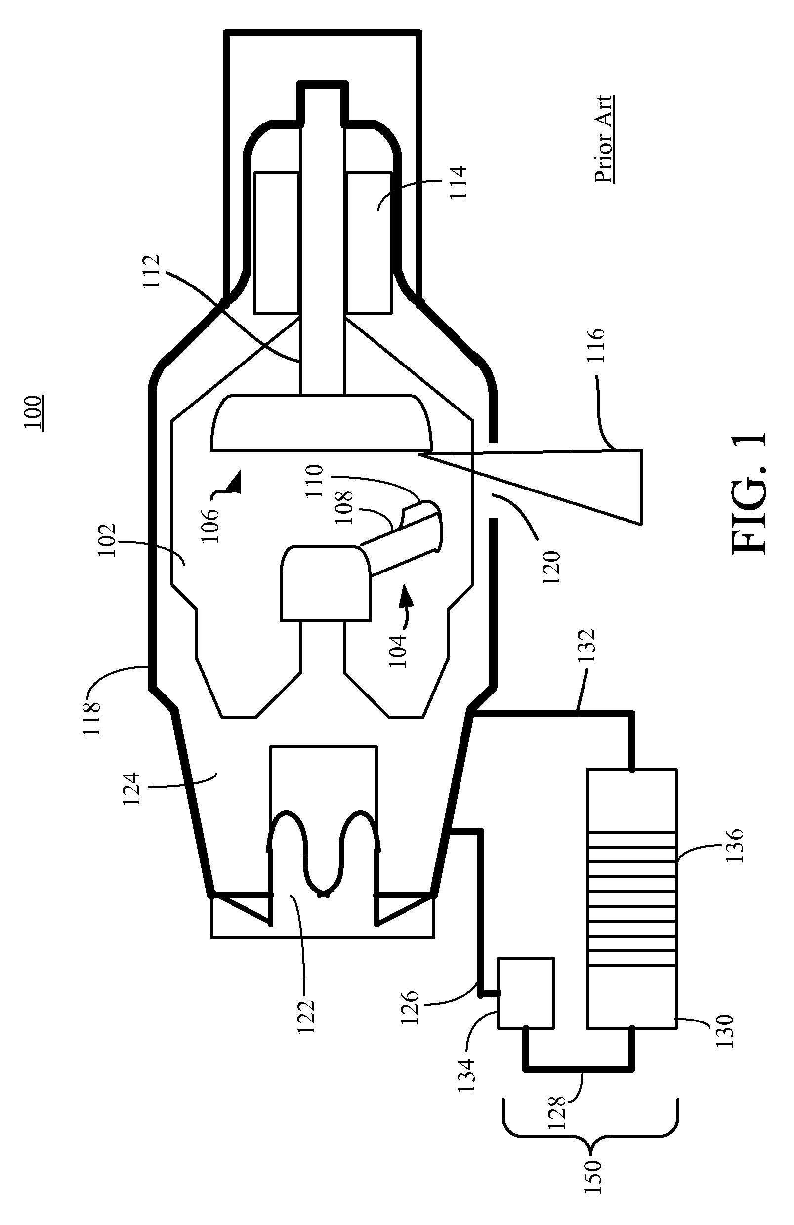
[0019]The detailed description is divided into four sections. In the first section, a conventional X-Ray system and cooling system are described. In the second section, an overview of an improved computed tomography (CT) imaging system is provided. In the third section, apparatus of the improved CT imaging system are provided. Finally, in the fourth section, a conclusion of the detailed description is provided.

Conventional X-Ray and Cooling Systems

[0020]FIG. 1 is a cross-sectional diagram of...


PUM


Abstract

An X-Ray tube is provided. The X-Ray tube includes a frame structure surrounding at least a portion of an electron beam source and an electron beam target. The frame structure has a cooling system integrated therein. The cooling system includes at least one air / fin layer; and a sub-cooled working fluid in thermal contact with the at least one air / fin layer, the sub-cooled working fluid being adapted to undergo a phase change in response to heat introduced to the frame structure by one or more of the electron beam source and the electron beam target, wherein the phase change facilitates transfer of the heat to the at least one air / fin layer.

Description

FIELD OF THE INVENTION[0001]This invention relates generally to X-Ray imaging devices, and more particularly to cooling techniques for X-Ray imaging devices.BACKGROUND OF THE INVENTION[0002]Computed tomography (CT) imaging systems are a commonly used medical imaging tool. CT imaging, also sometimes referred to as computerized axial tomography (CAT) scanning, is based on the variable absorption of X-Rays by different tissues. CT imaging systems generate cross-sectional images of a subject.[0003]A typical CT imaging system includes an X-Ray tube and a series of X-Ray detectors, mounted opposite the X-Ray tube, on a circular gantry. During imaging, a patient is placed on a table that passes through the center of the gantry. As the patient passes through the gantry, the gantry rotates around the patient. The X-Ray tube and X-Ray detectors on the gantry capture images of the patient from many different angles. A computer then compiles these images and produces a three-dimensional represe...

Claims


Application Information

Patent Timeline
Patent Type & Authority Patents(United States)
IPC IPC(8): H01J35/10
CPCH01J35/16H01J2235/1216H01J2235/165H01J2235/16H01J2235/1283
Inventor KENDALL, CHARLES B.ROGERS, CAREY SHAWN
Owner GENERAL ELECTRIC CO
Learn More