High frequency test fixture

a test fixture and high frequency technology, applied in the field of test fixtures, can solve the problems of repeatability in testing, change in test measurement, and inability to seller flexible circuit board traces, and achieve the effect of less errors in testing optical components, high repeatability and predictable testing

Inactive Publication Date: 2007-06-26
II VI DELAWARE INC
View PDF1 Cites 3 Cited by
  • Summary
  • Abstract
  • Description
  • Claims
  • Application Information

AI Technical Summary

Benefits of technology

[0015]Advantageously, the embodiments described above allow for repeatable testing to be performed. By allowing optical components and their leads to be consistently secured in a similar fashion each time, testing is highly repeatable and predictable. This results in less errors in testing optical components.

Problems solved by technology

For example, it may not be desirable to solder the flexible circuit board traces as would be done in a final installation because repeated soldering and desoldering may be harmful to the fiber optic component.
One drawback of the test board described above relates to repeatability in testing.
Thus, a shift in the fiber optic cable connected to the TO can may cause a change in test measurements.
Further, the test apparatus described above may be time consuming to use.
To prepare each component for test may require a significant amount of time, including mounting and positioning the component for testing.

Method used


Image

  • High frequency test fixture
  • High frequency test fixture
  • High frequency test fixture

Examples


Embodiment Construction

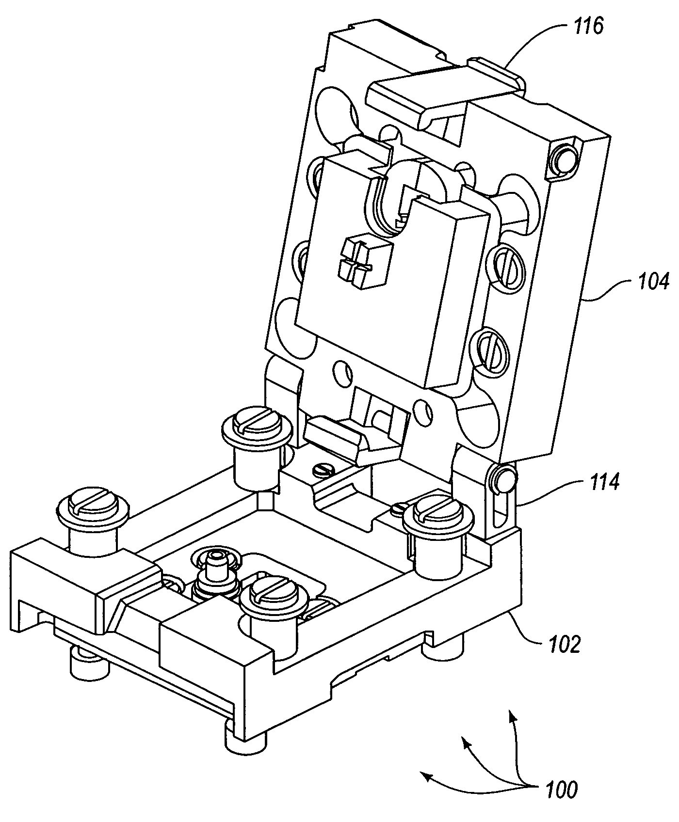
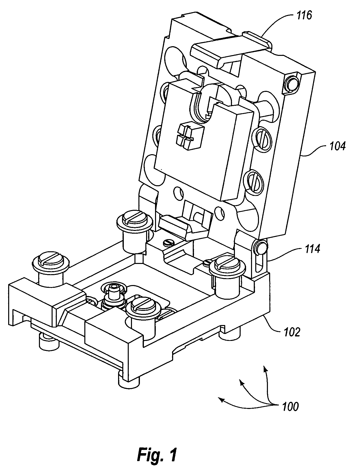
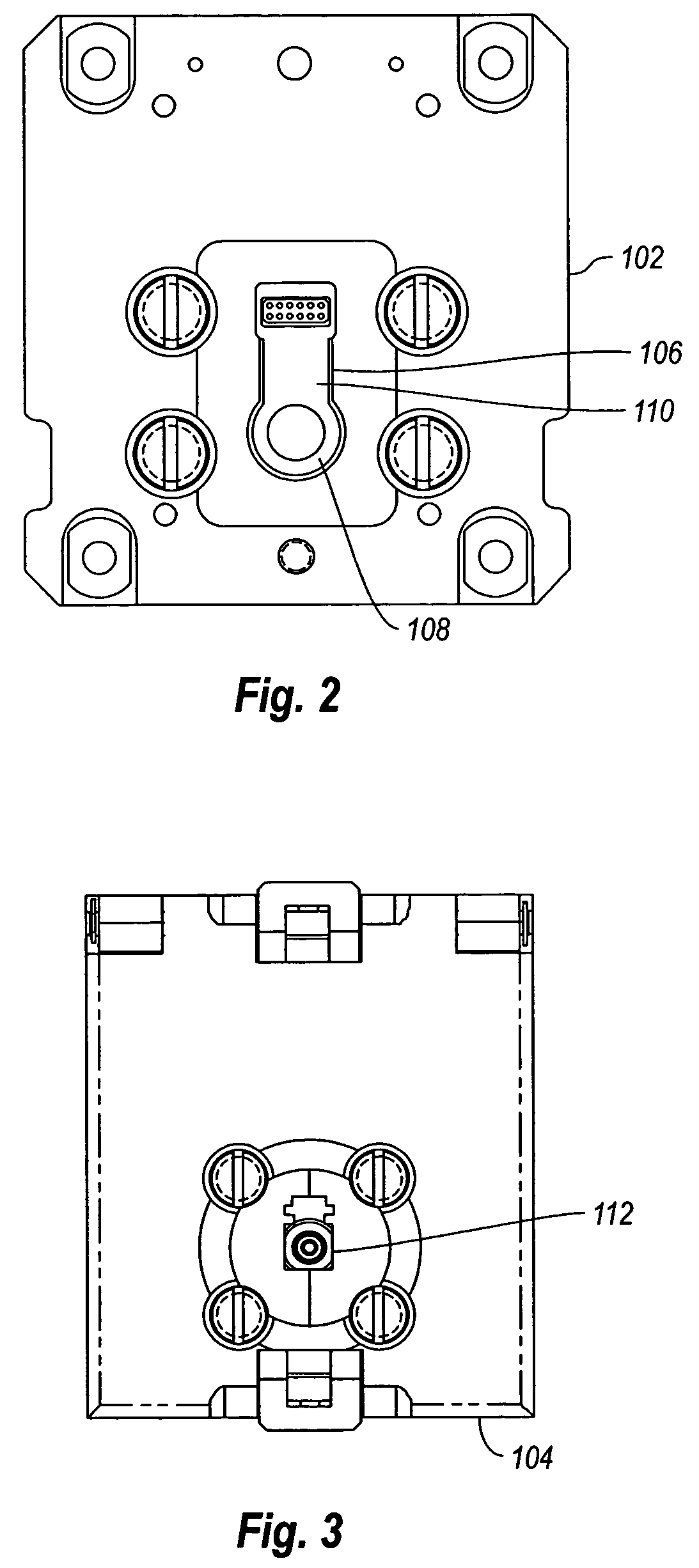
[0021]Embodiments disclosed herein include a test fixture that allows optical components to be positioned consistently in the test fixture. The test fixture further includes an optical fiber connector receptacle, such as an LC or SC receptacle, which allows an optical fiber to be optically coupled to the optical component under test. The test fixture allows for consistent positioning and alignment of optical fibers and optical components which translates into consistent test results.

[0022]As mentioned previously, the test fixture may be optimized with various types of receptacles depending on the type of component for fiber used for testing. For example, the receptacle may be an LC type connector. Alternatively, the receptacle may be an SC type receptacle. While not enumerated here, other receptacle types may be used.

[0023]Further, the test fixture may be designed to operate various types of optical devices. For example, the test fixture may include pogo pins for contacting traces o...


PUM


Abstract

An apparatus for testing optical components. The apparatus includes a component cavity. The component cavity includes a package portion generally including fit tolerances but otherwise including a similar size and shape of an optical component to be tested. The component cavity further includes an electrical interface portion that can hold electrical interface leads of the optical component. The apparatus further includes an optical fiber interface optically connected to the cavity. The optical fiber interface mates with an optical fiber. The optical fiber is connected optically to the optical component being tested.

Description

BACKGROUND OF THE INVENTION[0001]1. The Field of the Invention[0002]The invention is directed to test fixtures. More specifically, the invention is directed to test fixtures for use in testing optical components.[0003]2. Description of the Related Art[0004]Modern computing involves the transmission of large amounts of data on networks formed of two or more computers. As the processing power of computers has increased, there has been a need to keep pace with increased data handling capability across networks. One technology that facilitates the transmission of large amounts of data on the network is fiber-optics. Fiber-optics use light signals transmitted across glass or plastic fibers to communicate data. Fiber optic networks are able to transmit data at faster rates than conventional copper wire based networks. Additionally, fiber optic networks are less susceptible to noise and intrusion.[0005]To transmit data on a fiber-optic network a light generating device is needed. Commonly,...

Claims


Application Information

Patent Timeline
Patent Type & Authority Patents(United States)
IPC IPC(8): G02B6/00
CPCG02B6/4219
Inventor LALONDE, ANDRE
Owner II VI DELAWARE INC
Why Eureka
Try Eureka