
Vehicle body side structure
a side structure and vehicle technology, applied in the direction of roofs, transportation and packaging, vehicle arrangements, etc., can solve the problems of difficult to expect a great improvement in strength, and achieve the effect of increasing the strength of the vehicle body, efficient transfer/disperse, and high degree of control
- Summary
- Abstract
- Description
- Claims
- Application Information
AI Technical Summary
Benefits of technology
Problems solved by technology
Method used
Image

Examples
first embodiment
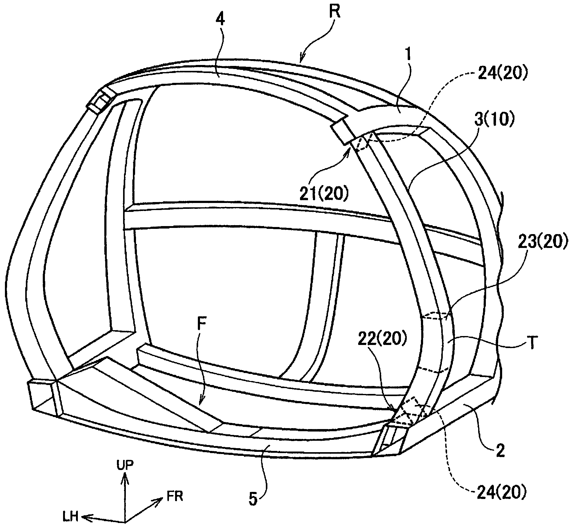
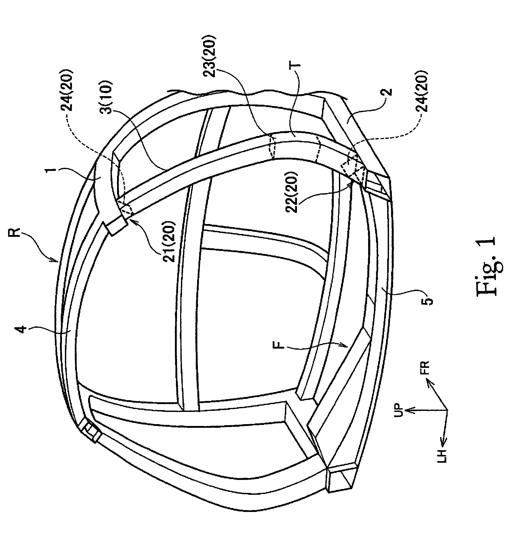
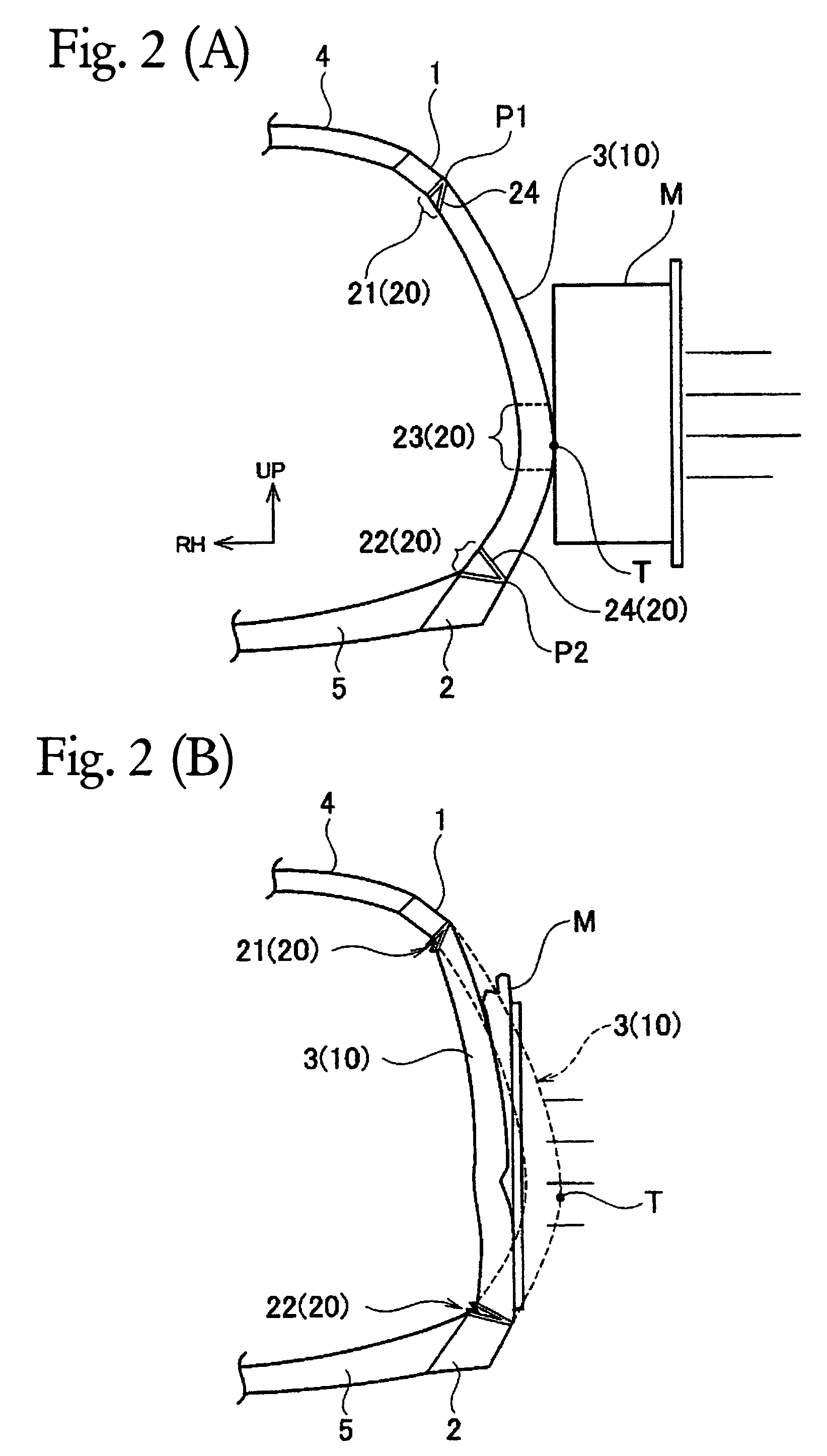
[0039]Referring initially to FIGS. 1-3, a vehicle body structure is illustrated in accordance with a first embodiment of the present invention. FIG. 1 is a rear perspective view of a passenger compartment portion of a vehicle body frame that includes a vehicle body structure in accordance with a first embodiment of the present invention. FIG. 2(A) is a schematic view illustrating the vehicle body structure of FIG. 1 just prior a side collision to illustrate a deformation mode of the first embodiment of the present invention during a side collision. FIG. 2(B) is a schematic view illustrating the vehicle body structure of FIG. 1 after the side collision of FIG. 2(A) to illustrate the deformation mode of the first embodiment of the present invention during a side collision. FIG. 3 is a graph comparing the vehicle body reaction force characteristic of the first embodiment to that of a conventional vehicle body structure during a side collision.
[0040]As shown in FIG. 1, the vehicle body ...
second embodiment
[0058]Referring now to FIGS. 4 to 6(B), a vehicle body structure in accordance with a second embodiment will now be explained. In view of the similarity between the first and second embodiments, the parts of the second embodiment that are identical to the parts of the first embodiment will be given the same reference numerals as the parts of the first embodiment. Moreover, the descriptions of the parts of the second embodiment that are identical to the parts of the first embodiment may be omitted for the sake of brevity.
[0059]FIG. 4 is a side perspective view of a vehicle body frame structure that includes a vehicle body structure in accordance with a second embodiment of the present invention. FIG. 5(A) is a cross sectional view of the center pillar of the second embodiment taken along section lines A-A of FIG. 4. FIG. 5(B) is a cross sectional view of the center pillar of the second embodiment taken along section lines B-B of FIG. 4. FIG. 5(C) is a cross sectional view of the cent...
third embodiment
[0074]Referring now to FIGS. 7, 8(A) and 8(B), a vehicle body structure in accordance with a third embodiment will now be explained. In view of the similarity between the first and third embodiments, the parts of the third embodiment that are identical to the parts of the first embodiment will be given the same reference numerals as the parts of the first embodiment. Moreover, the descriptions of the parts of the third embodiment that are identical to the parts of the first embodiment may be omitted for the sake of brevity.
[0075]FIG. 7 is a side perspective view of a vehicle body frame structure that includes a vehicle body structure in accordance with a third embodiment of the present invention. FIG. 8(A) is a schematic view illustrating the vehicle body structure of FIG. 7 just prior a side collision to illustrate a deformation mode of the second embodiment of the present invention during a side collision. FIG. 8(B) is a schematic view illustrating the vehicle body structure of FI...
PUM
 Abstract
Description
Claims
Application Information