Touch panel assembly

a technology of touch panel and assembly, which is applied in the direction of static indicating devices, instruments, lighting and heating apparatus, etc., can solve the problems of inevitably increasing the number of components and the functional performance of the light conductor plate, and achieve the effect of eliminating stickiness, eliminating stickiness, and being handled as easily

Inactive Publication Date: 2007-07-03
MINEBEA CO LTD +2
View PDF18 Cites 46 Cited by
  • Summary
  • Abstract
  • Description
  • Claims
  • Application Information

AI Technical Summary

Benefits of technology

[0018]With this configuration of the touch panel having no reinforcement member, the thickness of the touch panel itself is reduced. Further, since the housing frame to support the components of the spread illuminating device in an integral manner is provided with the touch panel positioning mechanism, and since the touch panel is fixed to the positioning mechanism, the absence of a reinforcement member is duly compensated for, thus ensuring the strength of the touch panel.
[0029]According to claim 12 of the present invention, the housing frame may be a resin molded part. This configuration increases the degree of freedom in selecting the shape of the housing frame and allows the housing frame to be formed with a touch panel positioning mechanism. In addition, if engagement mechanisms for engagement with a bottom frame of a sheet metal are formed directly in the housing frame, resin parts can be omitted that are conventionally provided in the bottom frame as independent members for attachment of the touch panel assembly.

Problems solved by technology

The conventional touch panel assembly 1 having the above configuration, however, has the following problems.
If the touch panel support plate 17 is removed for reduction of the thickness, when the first resistor layer 12 of the touch panel 10 is pressed for operation, the second resistor layer 13 is deformed and brought into contact with the light conductor plate 22 possibly giving damages to the light reflecting pattern, which results in a problem that the functional performance of the light conductor plate 22 is deteroprated.
Further, when the bottom frame 28 is screwed to a case (main body) of a communication terminal or the like, resin spacers must be disposed at screwing positions, which inevitably increases the number of components.

Method used


Image

  • Touch panel assembly
  • Touch panel assembly
  • Touch panel assembly

Examples


Embodiment Construction

[0040]The best mode for carrying out the invention will hereinafter be described with reference to the drawings. Components, etc. having the same or corresponding ones in the conventional technique are given the same reference symbols, a detailed explanation thereof will be omitted.

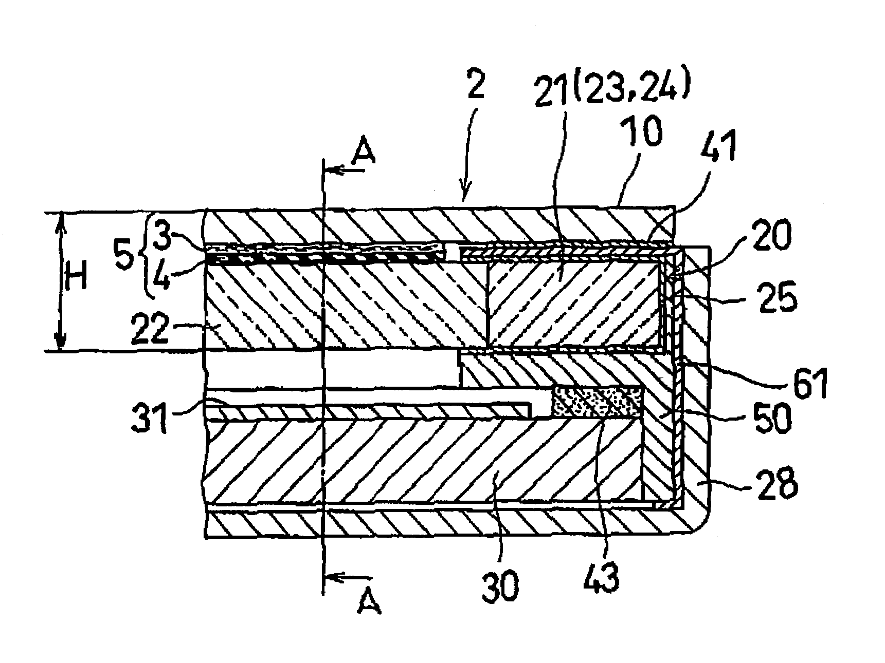
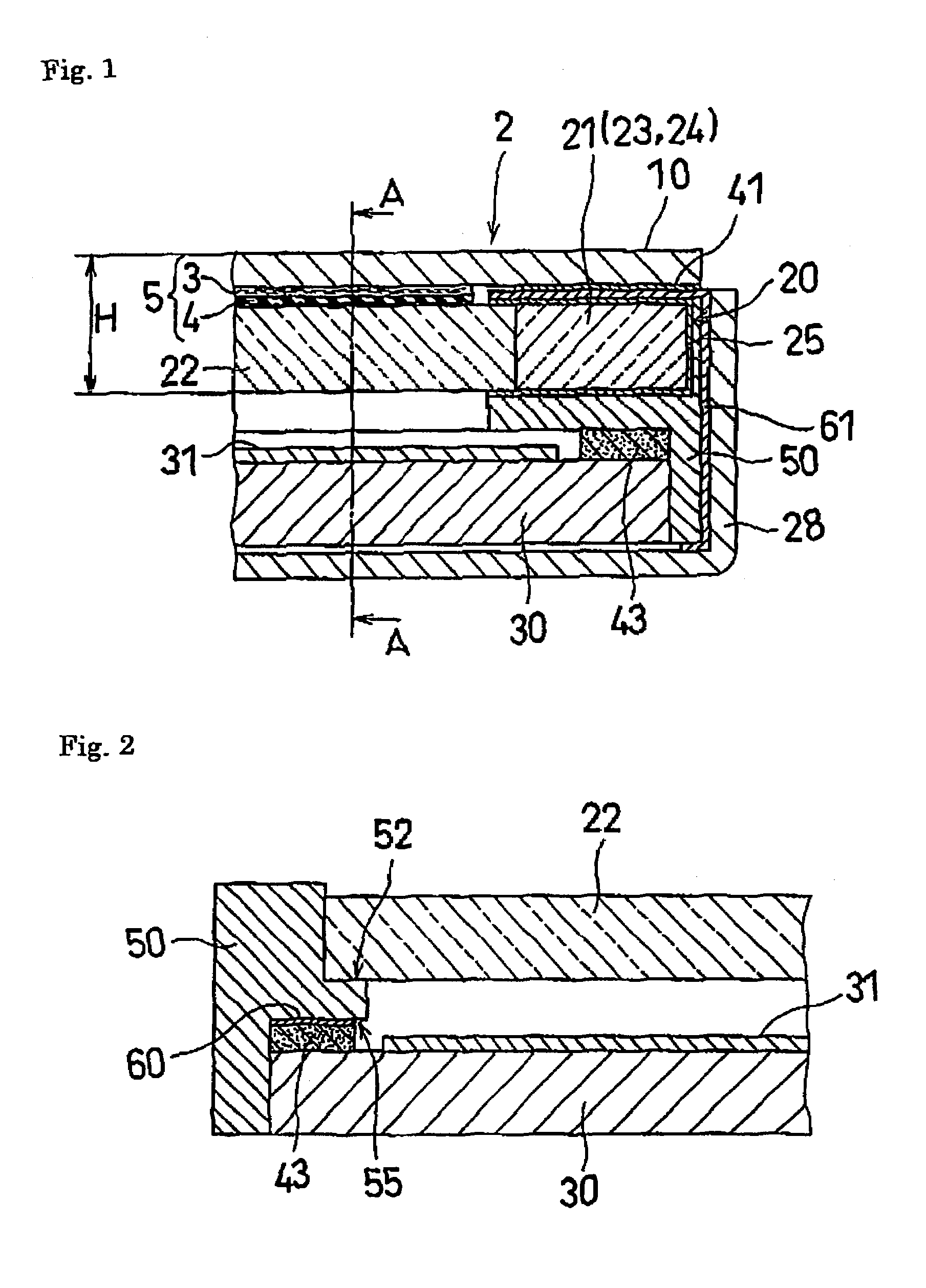
[0041]In the following description, such terms as “top surface,”“bottom surface,”“side surface,”“above,”“below,” and “beside” are used for the convenience of description for expressing positional relationships between members in FIGS. 1 and 2 that are sectional views of a pertinent part of a touch panel assembly according to the best mode for carrying out the invention. Therefore, when a touch panel assembly according to the best mode for carrying out the invention is incorporated in an electronic product such as a cellular phone and a personal computer and is used actually, for example, the “top surface” may not necessarily be located above the “bottom surface.”

[0042]FIG. 1 is a sectional view of a perti...


PUM

PropertyMeasurementUnit
thicknessaaaaaaaaaa
thicknessaaaaaaaaaa
thicknessaaaaaaaaaa

Abstract

In a touch panel assembly, the thickness of a touch panel is successfully reduced by using a touch panel 10 provided with no reinforcement member. A housing frame 50 that supports the components of a front light unit 20 in an integral manner is provided with a touch panel positioning mechanism, and the touch panel 10 is fixed to the positioning mechanism, whereby the absence of a reinforcement member is duly compensated for, thus ensuring the strength of the touch panel 10. Deformation of the touch panel 10 that occurs when the touch panel 10 is pressed for operation can be attenuated by a transparent buffer member 5 disposed between the touch panel 10 and a light conductor plate 22. Therefore, the touch panel 10 deformed is prohibited from contacting and damaging the light conductor plate 22, thus preventing the light conductor plate 22 from deteriorating in its functional performance. Consequently, reduction in dimension and reduction of the number of components can be achieved without deteriorating the functional performance of the touch panel assembly.

Description

TECHNICAL FIELD[0001]The present invention relates to a touch panel assembly that is disposed close to the display screen of a display device such as a liquid crystal display device, and that generates, when an operator presses the panel surface (corresponding to the display screen) at a desired position with a pen or his or her finger on the basis of information displayed on the display screen, a prescribed signal corresponding to the pressed position.BACKGROUND ART[0002]Touch panels of this type allow the area corresponding to the display screen of the display device to be used for both information display and information input thereby increasing the efficiency of utilization of that area. Therefore, the demand for touch panels of this type is becoming increasingly greater for use in small-size information processing devices and communication devices, in particular, portable communication terminals and the like.[0003]FIG. 8 is a sectional view of a conventional touch panel assembl...

Claims


Application Information

Patent Timeline
Patent Type & Authority Patents(United States)
IPC IPC(8): F21V7/04G02F1/1333G02F1/1335G09G3/36G09G5/00G02F1/13G02F1/133G02F1/13357
CPCG02F1/133308G02F1/13338G02F2001/133616G02F1/133616G06F3/041
Inventor KAWASHIMA, SATOSHICHOUSA, YOSHITAKATAKAGI, TAKAYUKINISHIKAWA, KAZUHIROHASHIMOTO, TAKAO
Owner MINEBEA CO LTD
Why Eureka
Try Eureka