Microarray hybridization device having bubble-fracturing elements

a hybridization device and microarray technology, applied in the field of microarray hybridization devices having bubble-fracturing elements, can solve the problems of large bubbles breaking up into microbubbles, and achieve the effect of increasing the volume of target solution used and the degree of mixing and uniformity of hybridization reaction

Inactive Publication Date: 2007-07-03
BIOCEPT INC
View PDF16 Cites 77 Cited by
  • Summary
  • Abstract
  • Description
  • Claims
  • Application Information

AI Technical Summary

Benefits of technology

[0016]A novel approach has been developed for generating sufficient and consistent mixing of small target solution volumes within a hybridization chamber. Unlike conventional bubble methods that utilize one or a few relatively large bubbles; this approach utilizes a multitude of much smaller bubbles which greatly increase the degree of mixing and uniformity of the hybridization reaction across the surface of the entire microarray. The cost is equivalent to other gasket-based hybridization chambers, and the volume of target solution used in the hybridization chamber is also similar.
[0017]In these improved devices, microbubbles are generated though the use of bubble fracturing elements that may take the form of teeth-like projections that protrude or project laterally into the interior volume of the hybridization chamber. As the devices are manipulated, large bubbles break up into microbubbles when they encounter such bubble fracturing elements in their path. As a result of such creation of microbubbles, there are far greater numbers of possible paths for bubbles to follow as result of movement of the device, and this leads to better solution mixing across the surface of the microarray. It is believed that the plurality of paths along which these microbubbles travel assure the amount of internal agitation of the target solution that is desired for thorough hybridization in a chamber which typically holds target solution in a volume of from 50 μl to 800 μl.
[0018]In one particular aspect, a microarray hybridization device which comprises a flat substrate having a surface to which a microarray of reactive moieties can be attached, liquid barrier means juxtaposed with said surface to create a chamber in which said microarray is located, and means closing said chamber so said device may be manipulated without loss of liquid target solution that fills said chamber except for a gaseous bubble included therein, said barrier means having inwardly facing surfaces which border said chamber, which surfaces are formed with a plurality of bubble-fracturing elements that extend laterally into said chamber so that, when said device is moved so that a liquid target solution in said chamber moves along said surface from one boundary of said chamber to another boundary, a bubble initially in said chamber is ruptured into a plurality of microbubbles that then assure very effective distribution of the liquid target solution in said chamber across the entire microarray, driven by movement of said microbubbles.
[0019]In another particular aspect, a method of effecting hybridization between probes and a target solution, which method comprises providing a flat substrate having a surface to which a microarray of reactive probe moieties are attached, juxtaposing a perimeter liquid barrier with said surface to create a chamber, in which said microarray is located, and closing said chamber so said substrate may be manipulated without loss of liquid target solution, filling said chamber with a target solution and a gaseous bubble, and moving said substrate to cause the target solution to move from one boundary of said chamber to another with at least one such boundary being shaped so that as a result of such movement the bubble in said chamber is ruptured into a plurality of microbubbles that then assure very effective distribution of the liquid target solution across the entire microarray, driven by subsequent movement of such microbubbles.

Problems solved by technology

As the devices are manipulated, large bubbles break up into microbubbles when they encounter such bubble fracturing elements in their path.

Method used


Image

  • Microarray hybridization device having bubble-fracturing elements
  • Microarray hybridization device having bubble-fracturing elements

Examples


Embodiment Construction

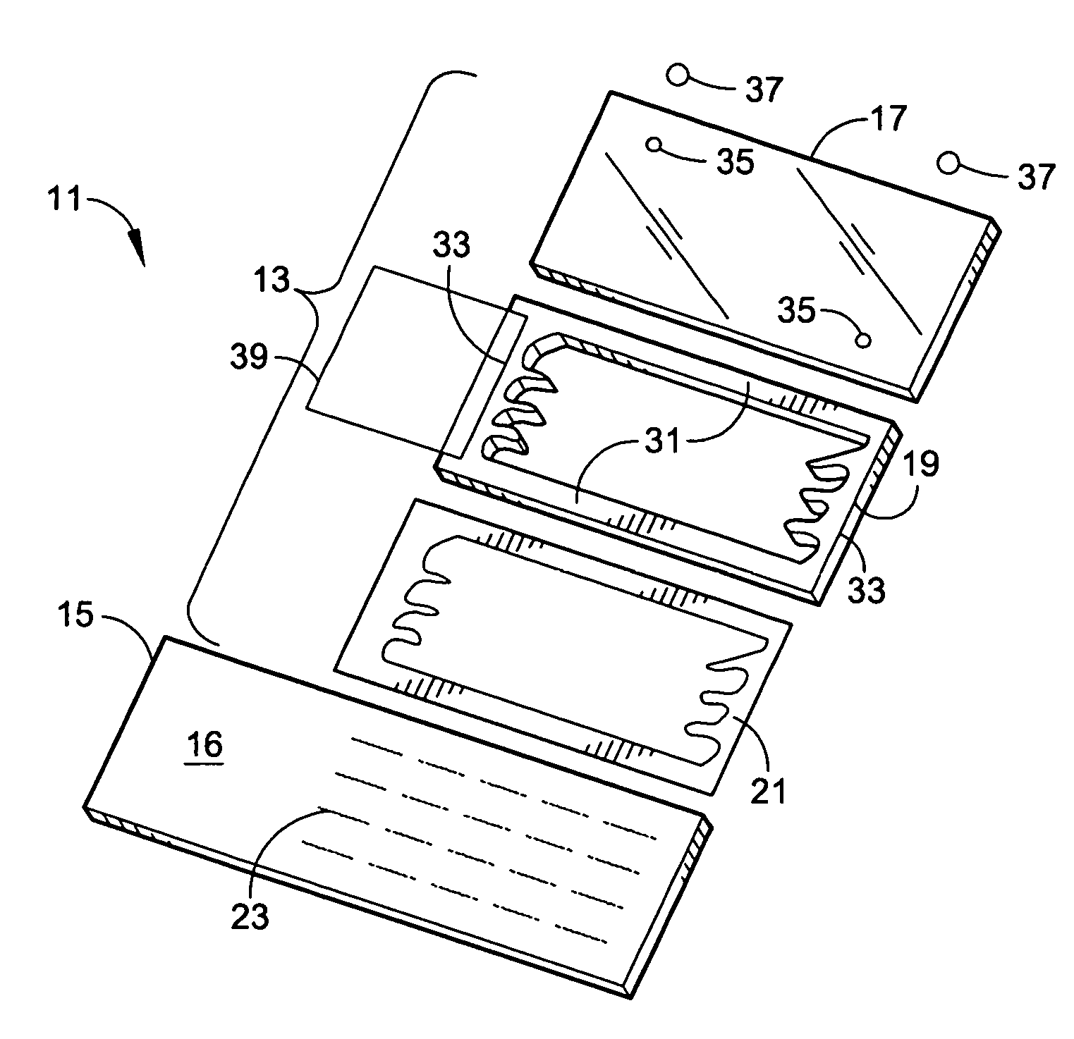
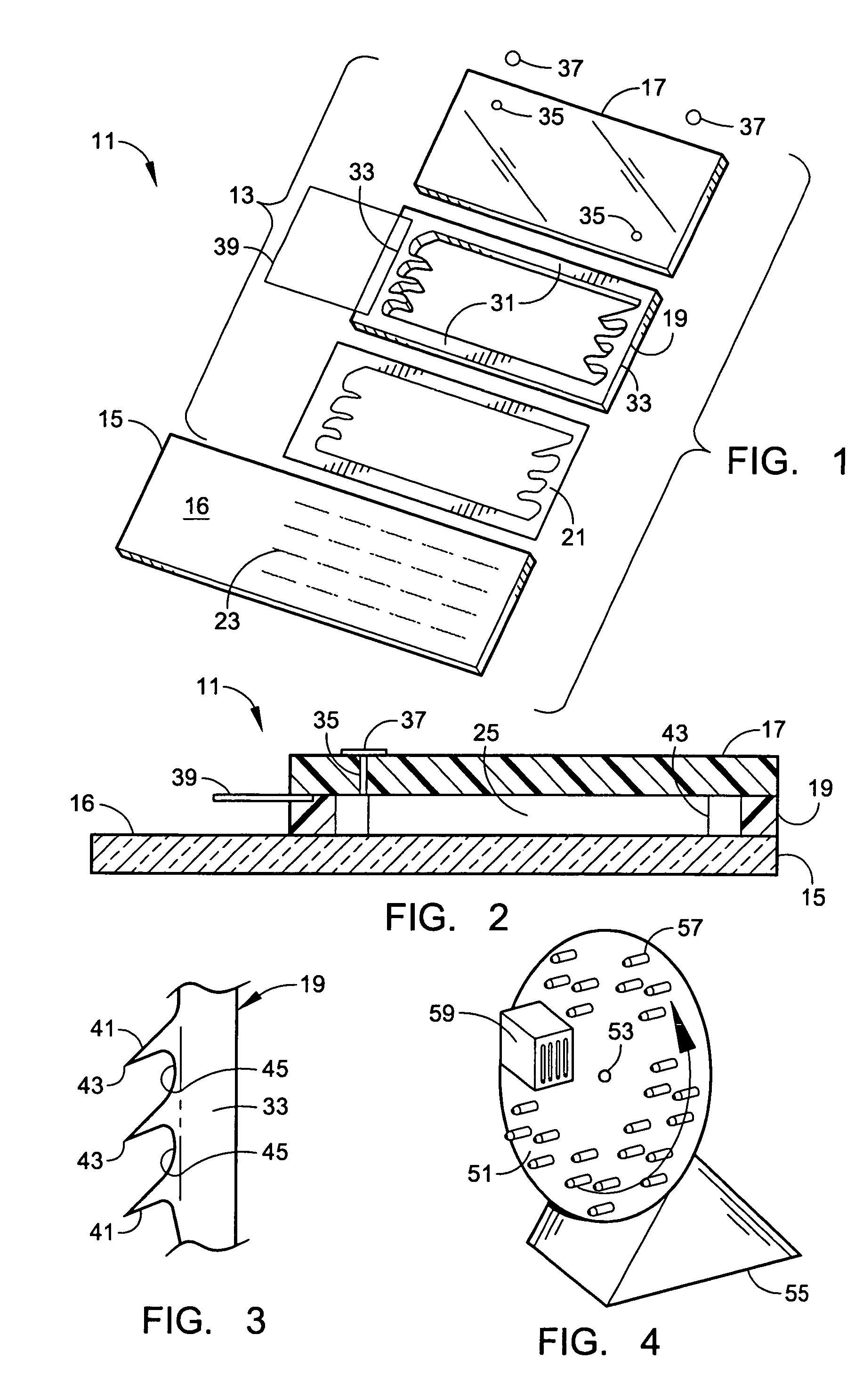
[0025]Illustrated in FIGS. 1 to 3 is an example of a microarray hybridization device 11 embodying various features of the present invention. Shown are the components of a cover and gasket subassembly 13 which bind to a glass slide 15 or the like to create a sealed hybridization chamber; the subassembly includes a flat cover 17 and a peripheral gasket 19.

[0026]The glass slide 15 provides a flat substrate upon which a microarray can be attached. Although the substrate 15 may be a standard glass laboratory slide, any other flat surface-providing object could be used that would be suitable for carrying biological samples. For example, they could be made of polymeric material instead of glass or any other suitable impervious material to which probe-carrying microdots might be applied. A standard laboratory slide 15 may be rectangular in shape having dimensions of 1×3 in. Of course other sizes and / or shapes could be used, but standardization is desirable for microassay hybridization react...


PUM

PropertyMeasurementUnit
heightaaaaaaaaaa
volumesaaaaaaaaaa
volumesaaaaaaaaaa

Abstract

A novel hybridization device that improves the efficiency and consistency of microarray hybridization reactions by achieving a greater degree of internal mixing of target solution. The device provides a gasket-and-cover-type chamber wherein solution mixing is achieved by the creation of a multitude of microbubbles. One or more of the inner walls that define the chamber contain bubble-rupturing elements that extend into the chamber and terminate in sharp edges. They are typically located on opposite sides of a rectangular chamber and are pointed in a direction opposing bubble movement. Their interference with larger bubbles causes their breakup into microbubbles which travel separate and distinct paths as a result of external agitation and thereby provide improved solution mixing that results in a uniform distribution of target molecules to the probe molecules bound to the substrate. The sensitivity and consistency of the hybridization reaction is significantly increased.

Description

FIELD OF THE INVENTION[0001]This invention relates to devices for effectively and efficiently carrying out hybridization of microassays using only relatively small amounts of the target solution and more particularly to improved devices of the type referred to generally as gasket-type or gasketed hybridization chambers which are designed to achieve thorough mixing in such a chamber containing a microassay with only 50 or a few hundred microliters of target solution.[0002]Hybridization of microarrays is frequently carried out by exposing “probe” molecules bound to a microscope slide surface to a solution of “target” molecules. There are presently four mainstream methods for hybridizing microarrays in this general way; they are referred to as coverslips, gasketed hybridization chambers, microscope slide mailers, and automated hybridization instruments. Choice of which method to implement often depends on factors such as probe and / or target availability, reagent and hardware costs, per...

Claims


Application Information

Patent Timeline
Patent Type & Authority Patents(United States)
IPC IPC(8): C12M3/00G01N15/06G01N33/48C12M1/00C12Q1/68B01F33/40B01J19/00B01L3/00C40B60/14G01N35/00G01N35/02
CPCB01F9/002B01F13/02B01L3/50273B01L3/502746C12Q1/6837G01N35/00029B01F11/00B01F13/0059B01F2009/0092B01J2219/00484B01J2219/00493B01J2219/00533B01J2219/00659B01L2300/0636B01L2300/0822B01L2400/0457B01L2400/086C40B60/14G01N2035/00079G01N2035/00138B01F29/321B01F29/40221B01F31/00B01F33/40B01F33/30B01J19/00G01N35/02B01F29/00
Inventor HAHN, SOONKAPSTEADMAN, JHOBETSINBERG, PAVELWATANASKUL, TIMGERASSI, YEHUDIT
Owner BIOCEPT INC
Why Eureka
Try Eureka