Hemodynamic optimization system for biventricular implants

a technology of hemodynamic optimization and biventricular implants, applied in the field of biventricular implants, can solve the problems of inability to achieve functions that would otherwise be impossible or practicable, inflict pain and waste energy, and reduce mortality, improve overall quality of life, and alleviate symptoms.

Active Publication Date: 2007-07-03
MEDTRONIC INC
View PDF114 Cites 20 Cited by
  • Summary
  • Abstract
  • Description
  • Claims
  • Application Information

AI Technical Summary

Problems solved by technology

Deaths from cardiovascular diseases (“CVD”) is a very serious problem in the United States and throughout the world.
However, as technology has permitted, these devices are not the only ones which may be carried with a person.
These functions may simply be more economical than a mechanical or chemical counterpart, but will often provide functions that would otherwise be impractical or impossible to achieve.
The entire probability density function need not always be developed; rather, it is sometimes sufficient to develop only particular values of the function at certain sampling points.
Currently anti-tachycardia systems detect arrhythmias primarily by sensing rate and perform inadequately in the differentiation of hemodynamically stable from unstable rhythms.
These devices, for example, may fire during a stable supraventricular tachycardia (SVT), inflicting pain and wasting energy.
Damage to the heart may result.
It is believed that the “rate-only” system, on the other hand, may be too sensitive, delivering cardioverting and defibrillating pulses too often or too soon, no hemodynamic parameter having been taken into consideration.
One drawback with many current systems is that they function primarily as a rate-only or single-hemodynamic-parameter driven systems and may fire for nonmalignant as well as malignant tachycardias.
These firings are not benign; potentially endangering myocardium, wasting energy and inflicting pain on the conscious patient, all distinct shortcomings and disadvantages.
Furthermore, these devices operate in a single mode; that is, such systems apply therapy, such as cardioverting and defibrillating pulses to the myocardium automatically, without the option or opportunity for confirmation or intervention by medical personnel.
Such monitoring systems are currently worn on the patient's waist or over the shoulders, and no active treatment is offered, since ischemia is only identified after the recording is complete, and the tape is scanned.
Although pharmacological and pacer therapy have ameliorated symptoms and improved the survival of patients with chronic heart failure (CHF) and other cardiovascular disorders, CHF remains a progressive disease causing incremental morbidity and early mortality.
Left bundle branch block in structurally normal hearts results in loss of synchrony of ventricular contraction and impairs both regional and global left ventricular systolic function.
But in patients with ischemic or idiopathic dilated cardiomyopathy it further impairs already poor systolic function and may have a major clinical impact.
However, successful implementation of the physical and electronic technologies for the ever broader effective clinical application has been somewhat more elusive.
Among the various challenges faced are the varying underlying causes of a malfunctioning heart, the complexity of diagnosis and myriad of devices which may presently be required for appropriate application to a given root cause, the difficult set-up of these prior art devices for operation, and the risk of undesirable inappropriate functioning of the device.

Method used


Image

  • Hemodynamic optimization system for biventricular implants
  • Hemodynamic optimization system for biventricular implants
  • Hemodynamic optimization system for biventricular implants

Examples


Embodiment Construction

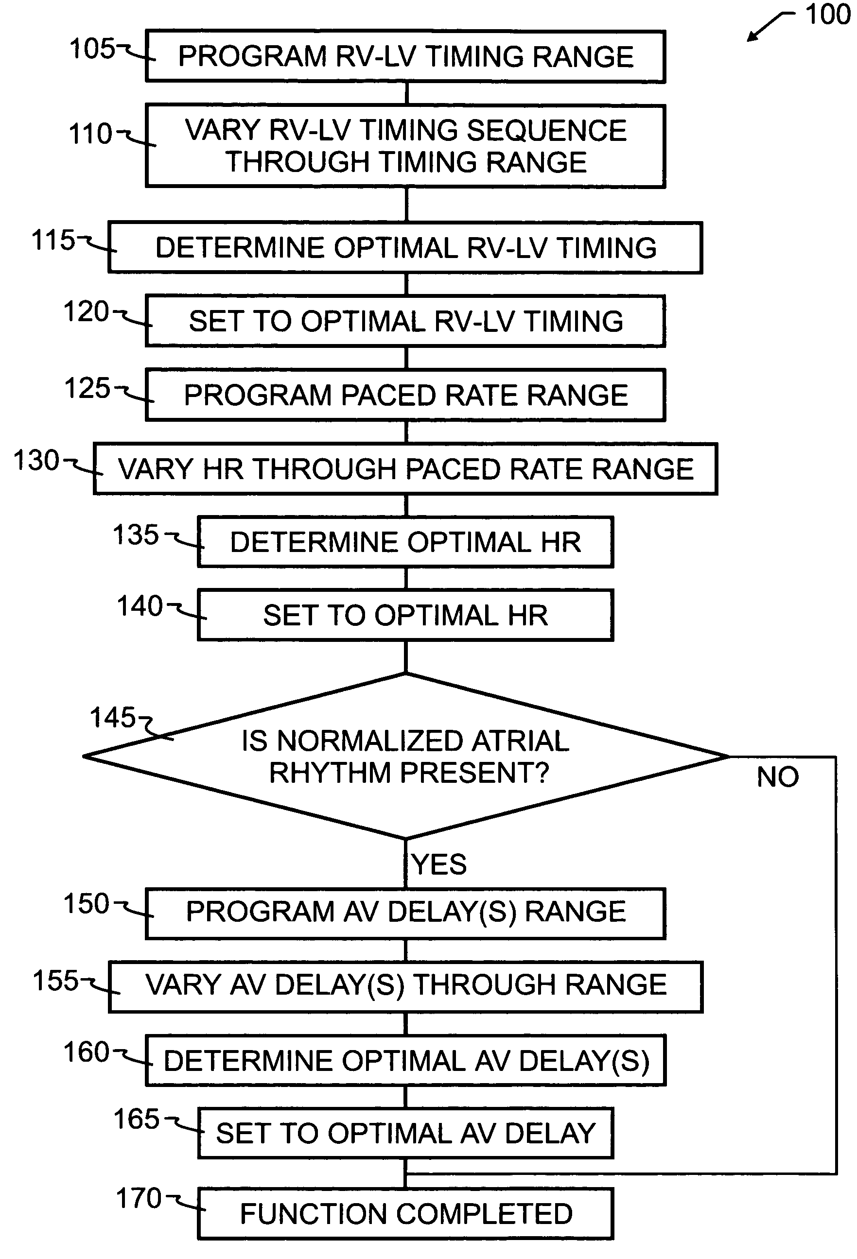
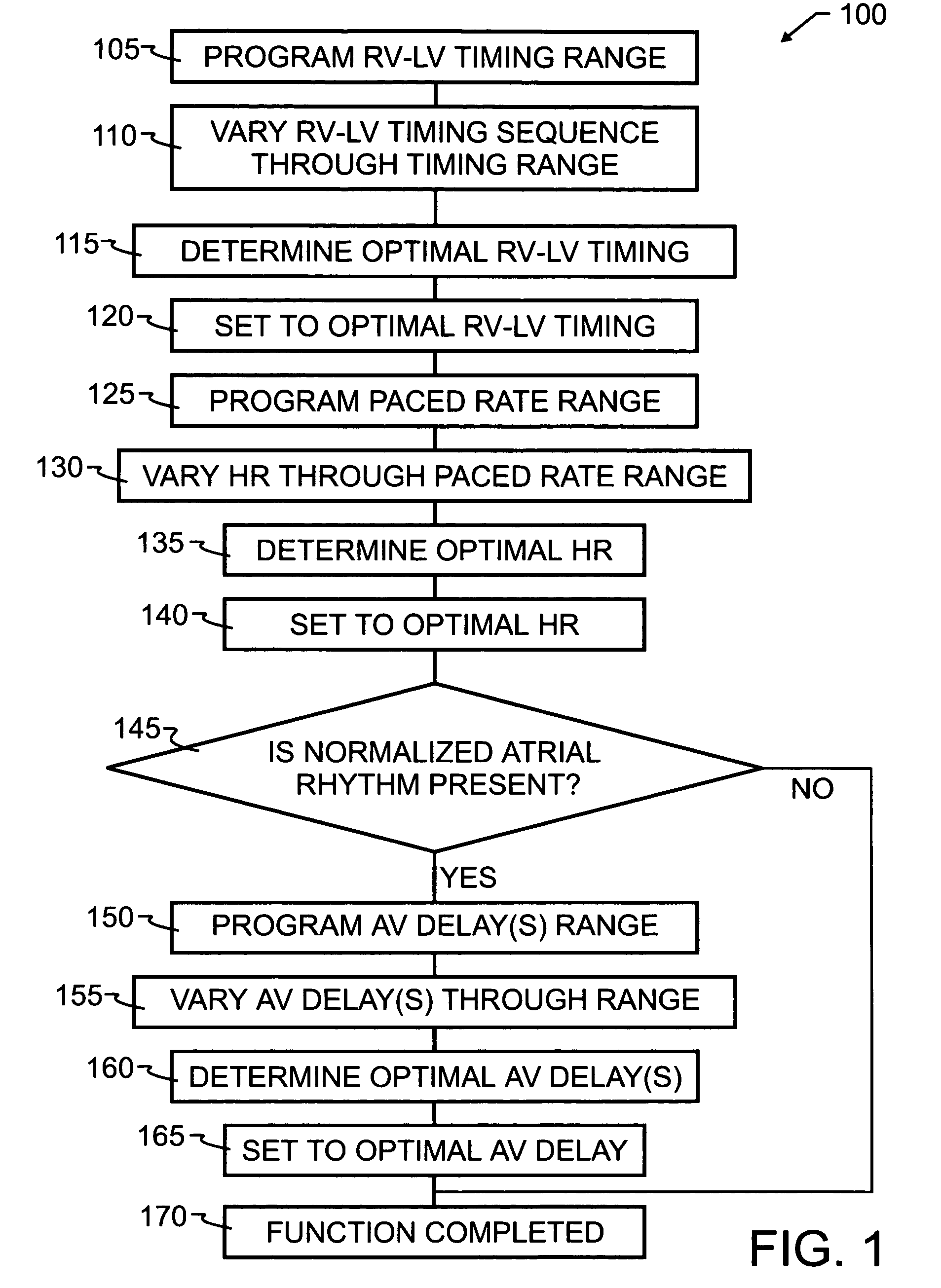
[0041]As has been recited in the prior art and herein above, one of the more significant obstacles in the design and implementation of biventricular pacing devices has been the selection and control of optimum pacing delays. These delays are known to vary by patient, and in some instances, by patient position and activity. The preferred embodiment method 100 of the present invention, illustrated by flowchart in FIG. 1, overcomes the limitations of the prior art by implementing a feedback loop in a biventricular implant, in order to automatically or selectively optimize both the atrioventricular delay and the RV-LV timing sequence.

[0042]In order to optimize the patient's clinical hemodynamic status, the biventricular implant will be programmed in accord with method 100 to go through a series of AV delay and RV-LV timing and heart rates sequences which scan the range of programmable values and apply those values to the patient's heart. Hemodynamic patient measurements will be recorded...


PUM


Abstract

A system for monitoring a patient and treating the malfunctioning heart of the patient, either in an automatic mode or in a semiautomatic mode, includes means which derive at least one physiologic signal from or related to the patient's circulatory system representative of hemodynamic status. A feedback loop is implemented in a biventricular implant, in order to automatically or selectively optimize the patient's clinical hemodynamic status. Accordingly, the biventricular implant will be programmed to go through a series of AV delay, RV-LV timing and heart rate sequences which scan a preselected range of programmable values and apply those values to the patient's heart. Hemodynamic patient measurements will be recorded and preferably graphed over those applied values. The optimal AV delay, RV-LV timing sequence and pacing rate can then be selected either manually by a technician, physician or other operator, or automatically via the implant in order to secure the best personalized timing sequence for the patient. Preferably, the implant will also be capable of automatically recording hemodynamic information and adjusting intervals, in order to optimize hemodynamics without third party intervention. Also preferably, the automatic adjusting feature can be selectively programmed on or off using the device programmer, to control manual or automatic intervention.

Description

CROSS REFERENCE TO RELATED APPLICATIONS[0001]This application claims priority to U.S. provisional patent application Ser. No. 60 / 530,072, filed Dec. 16, 2003 and naming the present inventor, the contents which are incorporated herein by reference in its entirety.BACKGROUND OF THE INVENTION[0002]1. Field of the Invention[0003]This invention pertains generally to biventricular implants, and more specifically to methods of operating those implants in order to manually, semi-automatically, or automatically optimize their operation.[0004]2. Description of the Related Art[0005]Deaths from cardiovascular diseases (“CVD”) is a very serious problem in the United States and throughout the world. Since 1900, CVD has been the No. 1 killer in the United States for every year (except for 1918).[0006]The CDC estimates that each year around 400,000 people die of heart disease in an emergency department or before reaching a hospital; this accounts for a very large percentage of all cardiac deaths. A...

Claims


Application Information

Patent Timeline
Patent Type & Authority Patents(United States)
IPC IPC(8): A61N1/00A61N1/362A61N1/365A61N1/368
CPCA61N1/3627A61N1/36514A61N1/3682A61N1/3684A61N1/36843
Inventor COHEN, TODD J.
Owner MEDTRONIC INC
Why Eureka
Try Eureka