Telescope sight mount for a firearm

a telescopic and firearm technology, applied in the field of firearm telescopic sight mounts, can solve the problems of high production cost, system failure to reliably clamp the sight, and inability to produce premium accuracy, so as to reduce the weight of the mount, and increase the clamping pressure

Inactive Publication Date: 2007-07-10
NTR GROUP VENTURES
View PDF19 Cites 18 Cited by
  • Summary
  • Abstract
  • Description
  • Claims
  • Application Information

AI Technical Summary

Benefits of technology

[0011]In one embodiment of the invention there can be two dowels extending from the front portion of the main body, each of which mate with a mating hole within the clamp portion. The dowels and the mating holes function to align the front portion and the clamp portion before and during horizontal tightening by the screws. The screws pass through clearance holes in the clamp portion and are received by threaded holes within the front portion of the mount. Tightening the screws into the front portion by way of the threaded holes serves to increase the clamping pressures exerted by the front and clamp portions onto the vent rib, and the screws of the present invention can be designed to exert very large clamping pressures.
[0012]The back portion of the main body functions to receive the telescopic sight. To decrease the weight of the mount, which can be made of 304 stainless steel, the back portion can be substantially hollowed out from back to front, and portions of the substantially hollowed-out region also include lightening holes which pass completely through the back portion of the main body to decrease the mass and weight of the mount. The back portion also can include lateral slots cut into its upper surface for receiving locking bolts from a telescope ring assembly, which is known in the art. Alternatively, T-6 aircraft aluminum, anodized to the desired color, can be used for weight reduction, or blued steel can be used for cost reduction.
[0013]While the size of the T-slot formed by the combination of the front portion and the clamp portion is compatible with a standard vent rib, there are varying sizes of vent ribs on the market. If the vent rib is larger or smaller than the standard sized T-slot, then the front and clamp portions of the mount can also be manufactured to accommodate the larger or smaller sized vent rib without compromising strength and stability. Alternatively, in another embodiment of the invention, an insert, or shim, can be made available to accommodate a smaller vent rib. The shim provides a certain amount of adaptability to utilize the present invention with a thinner vent rib.

Problems solved by technology

While shotguns with vent ribs have been highly advantageous in sports such as trap and skeet shooting, and general wing shooting, such sights do not readily lend themselves to rifle-like accuracy which would be useful in hunting big game and the like.
However, in recent years many local governments have become concerned about the use of high-powered rifles in their areas.
The hunter who already possesses a shotgun for hunting small game which is otherwise adequate does not have, at present, a means for reliably providing that same shotgun with a telescopic sight that can be conveniently installed to be rigidly affixed to the shotgun while in use and then later removed.
However, this system is not able to reliably clamp the sight strongly due to the thinness of thee plate, which has only a limited number of screw threads for fitting the screws.
While the prior art devices may be sufficient for the particular problems that they solve, such sights either involve the permanent altering of the gun, do not produce premium accuracy, are not amenable to mounting of a telescopic sight, and / or do not provide reliable, rigid mounting to withstand jolts from repeated firing.
Thus, even with these add-on type sights, the shotgun has not obtained its maximum accuracy.
Further, shotguns which are appropriate for use by younger hunters are generally too heavy for the user when an additional element such as a mount for a telescopic sight is added.

Method used


Image

  • Telescope sight mount for a firearm
  • Telescope sight mount for a firearm
  • Telescope sight mount for a firearm

Examples


Embodiment Construction

[0023]The term “detachable” as used herein refers to an attachment to a vent rib of a shotgun which is removable when such removal is desired. The detachable scope mount of this invention is an intermediate structure that attaches to the gun and to which the gun sight is attached. The terms “scope mount”, “telescopic sight mount” and “sight mount” as used herein are interchangeable, and refer to a mount onto which a telescopic sight can be attached and which also can be mounted to a firearm having a vent rib, such as a shotgun.

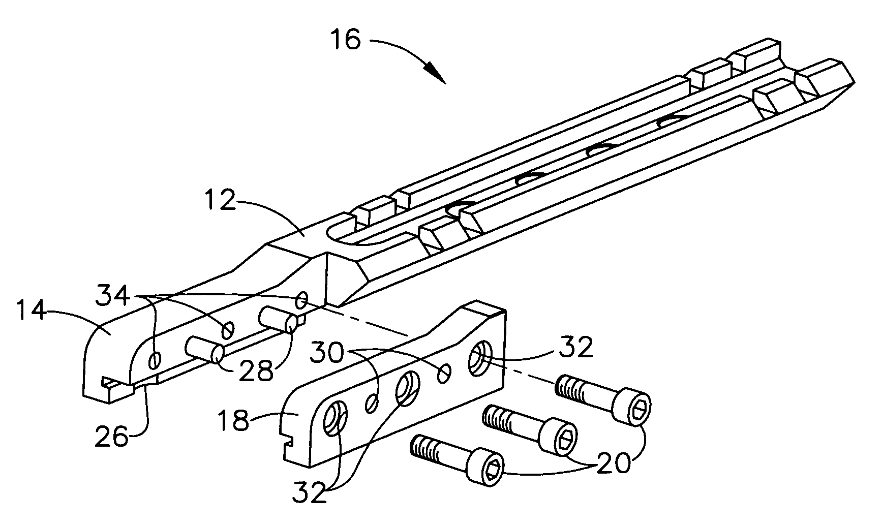
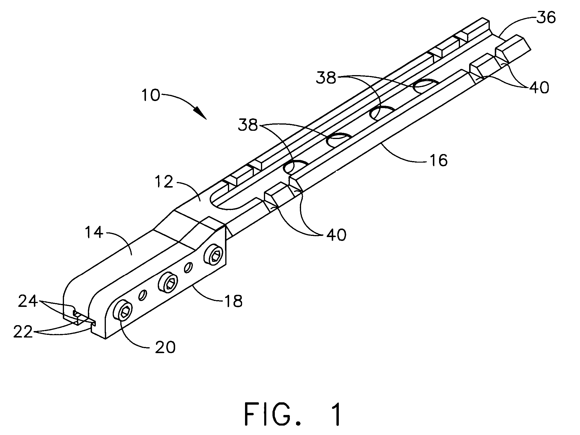
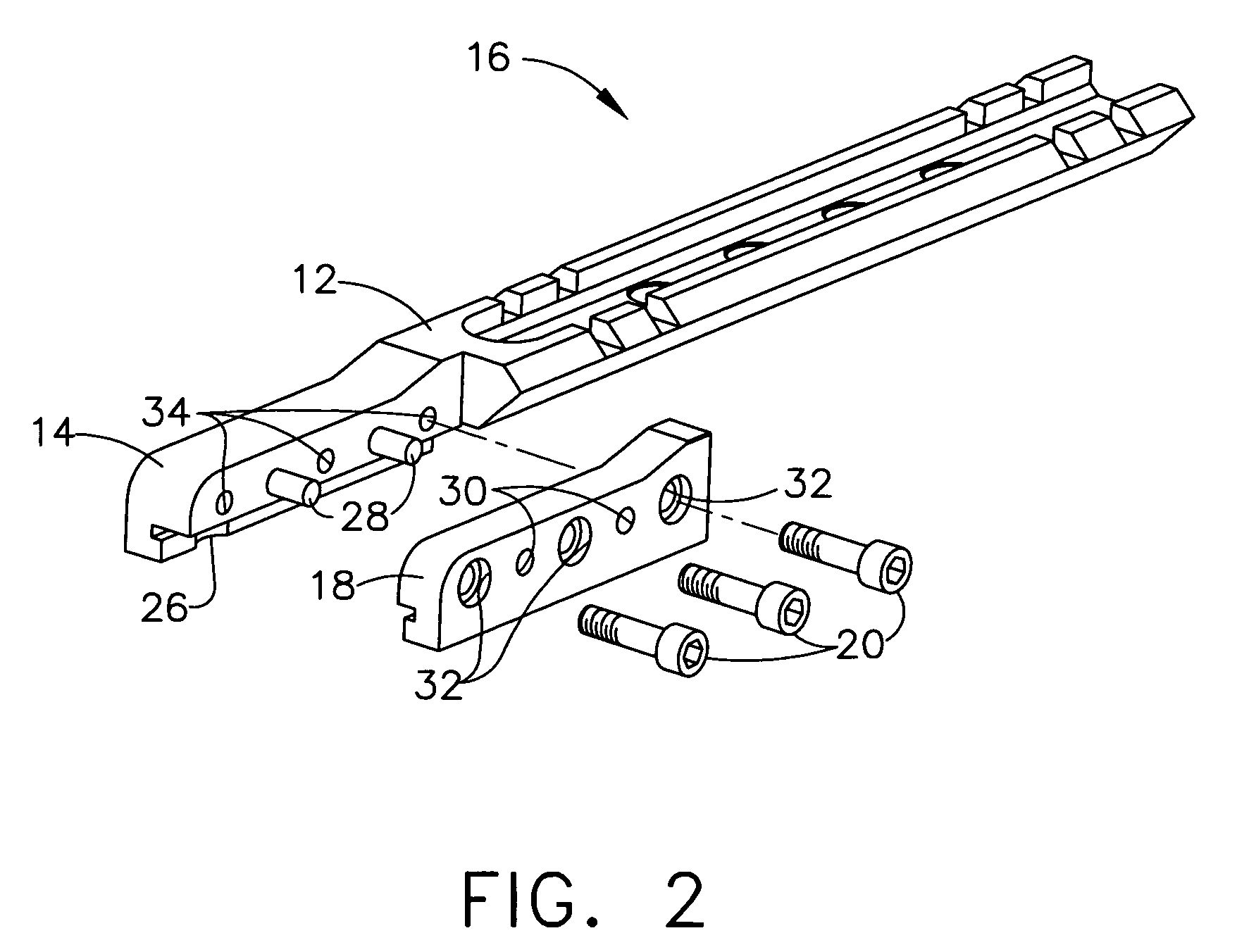
[0024]Referring now to the scope mount of the present invention shown in FIG. 1 of the drawings, the mount 10 includes a cantilevered main body 12 having a front portion 14 and a back portion 16. The front portion 14 is designed to cooperate with a clamp portion 18. Screws 20 adjoin the clamp portion 18 to the front portion 14. The front portion 14 has a lip portion 22 and a rib receiver 24. The clamp portion 18 likewise includes a lip portion 22 and a rib rec...


PUM


Abstract

The present invention is a telescopic sight mount for attachment to a firearm having a longitudinal vent rib on its barrel. The mount is readily attachable and detachable and includes a cantilevered main body having a front portion and a back portion, a clamp portion, and at least three clamping screws. The screws adjoin the front portion of the main body with the clamp portion and draw the front and clamp portions horizontally towards one another and into rigid clamping engagement with the vent rib. The back portion of the main body is able to receive and mount a telescopic sight. The mount can be rigidly mounted onto the firearm with stability sufficient to remain in place permanently despite recoil, and can also be easily detached from the firearm if desired.

Description

[0001]The present invention relates in general to readily attachable and detachable mounting systems for a shotgun or other firearm having a vent rib on its barrel. More particularly, the present invention relates to a mount for a telescopic sight which may be securely attached to and easily detached from a shotgun barrel having a vent rib.BACKGROUND OF THE INVENTION[0002]Shotgun barrels having ventilation ribs (“vent ribs”) have been successfully utilized to provide advantages in sighting and hitting a target with a shotgun. Such vent ribs have been advantageous in that they provide a flat clean sight plane for the shooter to look down and quickly superimpose the barrel onto the target. Also, vent ribs act to better dissipate heat which causes visual distortion after several shots have been fired from the shotgun. Vent ribs are normally the same size for all models and gauges of shotgun made by a single manufacturer. Although there are some shotguns with “odd” sized vent ribs, the ...

Claims


Application Information

Patent Timeline
Patent Type & Authority Patents(United States)
IPC IPC(8): F41G1/387
CPCF41G11/003
Inventor BLAIR, BRAD
Owner NTR GROUP VENTURES
Why Eureka
Try Eureka