Heat exchanger

Inactive Publication Date: 2007-07-10
THERMAGEN SA
View PDF50 Cites 24 Cited by
  • Summary
  • Abstract
  • Description
  • Claims
  • Application Information

AI Technical Summary

Benefits of technology

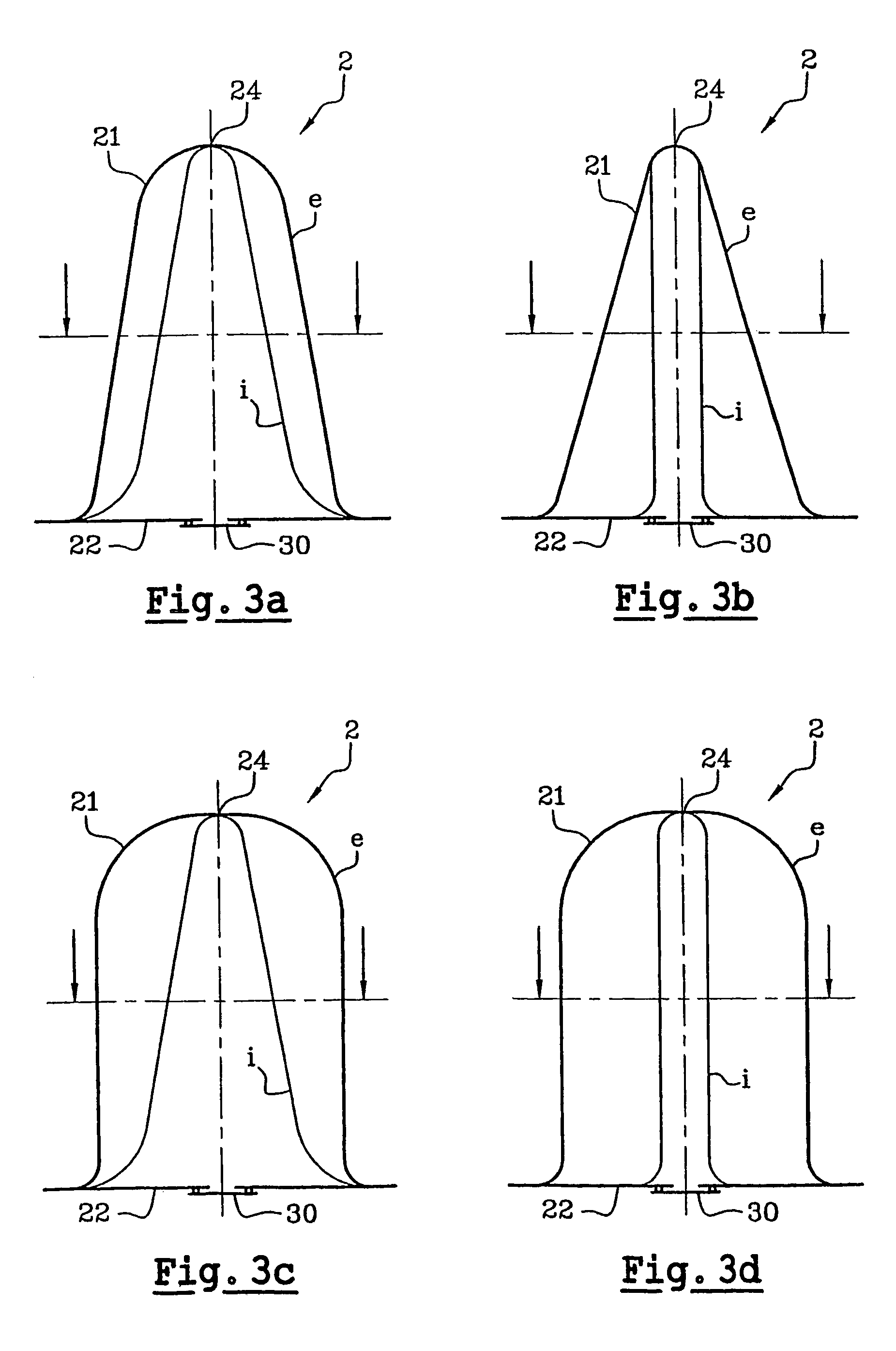
[0011]To this end, the present invention provides a heat exchanger the geometry and lay-out of which makes it possible to promote the speed of cooling of a drink on the principle of the evaporation of a cooling liquid at reduced pressure. Thus, the geometry of the exchanger favours the establishment of substantial convection currents in the drink in order to ensure its rapid cooling. This geometry moreover makes it possible to ensure a maximum heat exchange surface with the drink for a minimum space occupied by the exchanger.
[0012]Another objective of the invention is to generally apply the principle of cooling by evaporation under the effect of a reduced pressure to any device for cooling a liquid by the use of a heat e

Problems solved by technology

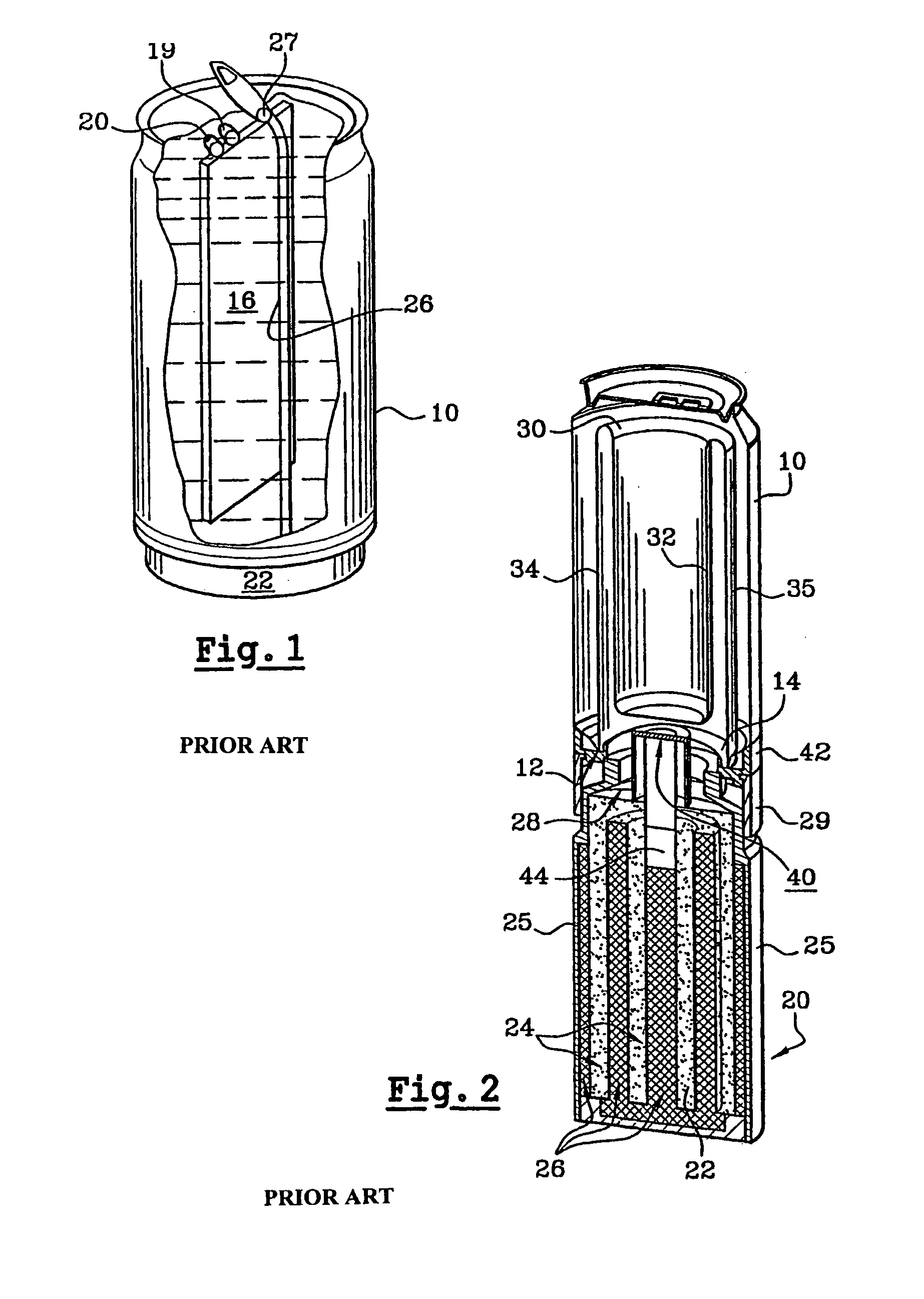
Another drawback of the device disclosed in the above-mentioned international applications relates to the quantity of metal necessary to produce this exchanger 30, therefore its cost.
Moreover, another drawback, linked to the particular geometry of the exchanger 30 disclosed in these international applications, lies in the requirement to use a gel to fix the cooling liquid in the exc

Method used


Image

  • Heat exchanger
  • Heat exchanger
  • Heat exchanger

Examples


Example

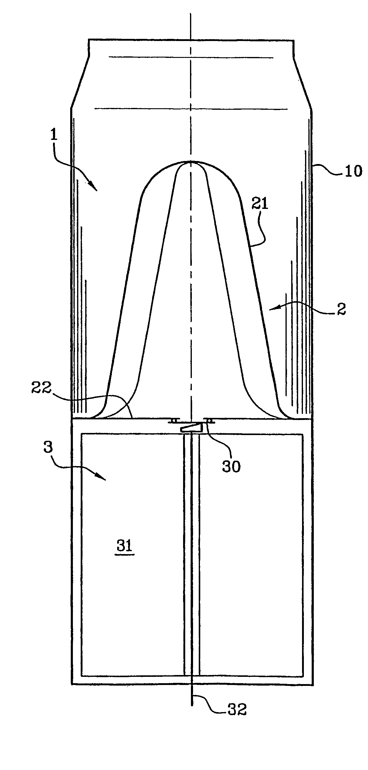
[0078]In a first embodiment variant, an illustration of which can be given by FIG. 5, the cooling dip tube comprises a heat exchanger according to the invention with a substantially conical cavity 2 linked to pumping means 31 by means of connection 30 integrated in the wall 22 forming the base of the cavity 2. The heat exchanger is then alone provided with its integrated means of communication 30 and must be linked to suitable pumping means 31, such as a mechanical or cryogenic vacuum pump or a cartridge under air vacuum containing desiccants, by a tube which can be flexible or rigid, fixed or removable.

Example

[0079]In a second embodiment variant, illustrated in FIG. 7, the cooling dip tube comprises a heat exchanger according to the invention with a substantially conical cavity 2 integral with pumping means by the wall 22 forming the base of the cavity 2. The heat exchanger is then provided with integrated means of communication 30 and suitable pumping means 31, such as a cartridge under air vacuum containing desiccants. The dip tube thus constitutes an autonomous cooling device, disposable or optionally reusable after regeneration.


PUM


Abstract

A heat exchanger for cooling a liquid comprising a cavity (2) containing a refrigerating liquid capable of evaporation under the effect of a depression maintained by a pump. The cavity includes at least a first wall (21) in contact with the liquid to be cooled, the first wall (21) being substantially conical such that its cross-sectional surface tapers from the base towards the top, and at least a second wall (22) forming the base of the conical shape and incorporating communication (30) between the cavity (2) of the exchanger and the pump.

Description

BACKGROUND OF THE INVENTION[0001]The present invention relates to a heat exchanger for the implementation of a cooling of a liquid by a method of evaporation and adsorption. The principle of such a method of cooling consists of evaporating a liquid under the effect of a reduced pressure maintained by pumping of the vapors of said liquid.[0002]The heat exchanger according to the invention is intended to be used in a receptacle in the form of a cooling dip tube or incorporated in a self-cooling drink container. The aim of the present invention is thus to allow the consumption of a drink at an ideal temperature at any place and at any time.[0003]The implementation of the method of cooling by evaporation and adsorption is known and has been the subject of numerous research projects in the prior art. Numerous devices have been proposed, combining a heat exchanger containing a liquid to be evaporated with a reservoir containing an adsorbent, in particular for application in self-cooling d...

Claims


Application Information

Patent Timeline
IPC IPC(8): F25B19/00F25B17/08F25D3/08F25B15/04F25D7/00F25D31/00
CPCF25B17/08F25D31/007F25D2331/805
Inventor JEUCH, PIERRE
Owner THERMAGEN SA
Why Eureka
Try Eureka