Removable end plug

a technology of end plugs and cylinders, applied in the direction of reciprocating piston engines, cylinders, positive displacement engines, etc., can solve the problems of easy thread breakage, difficult to attach removable ends, and substantially reducing thread strength at the thread location, so as to reduce concentrated shear stress and reduce low stress fiber breakage , the effect of easy disassembly

Active Publication Date: 2007-07-10
POLYGON
View PDF16 Cites 32 Cited by
  • Summary
  • Abstract
  • Description
  • Claims
  • Application Information

AI Technical Summary

Benefits of technology

[0012]An advantage of the present invention is that the cylinder can be easily disassembled utilizing common tools.
[0013]Another advantage of the present invention is that a common tube, such as a reinforced synthetic tube may be utilized.
[0014]Yet another advantage of the present invention is that the end plug is secured by an exterior split band that is associated with a groove on the outside surface of the cylinder.
[0015]Still yet another advantage of the present invention is that the clamping ring helps distributes the stresses into the composite, thereby reducing concentrated shear stresses.
[0016]Still yet another advantage of the present invention is that the clamping ring also applies radial compression pressure to the composite tube. This compression pressure tends to load the reinforcing fibers throughout the wall thickness of the composite more uniformly thereby reducing low stress fiber breakage.

Problems solved by technology

Air cylinders are often used in environments where hydraulic fluids would be undesirable, such as in food processing facilities.
However, in cases where tie rod designs are not desirable or permissible it becomes difficult to attach removable ends.
Problems associated with these methods relative to reinforced polymeric composite cylinders include: Cutting threads into a filament wound composite severs the reinforcing members of the composite thereby substantially reducing the shear strength at the thread location.
Upon repeated assembly the threads tend to break down easily due to low shear strength of the threads.
The conventional design for the use of retaining rings in a composite is not desirable due to the eroding of the groove in the composite cylinder tube by the metallic retaining ring under cycling conditions.
Bolting or pinning the end attachment by radial orientated fasteners around the circumference of the tube is not desirable due to the cutting of reinforcement through the entire thickness of the laminate at the holes, stress concentrations at the hole locations and potential micro-cracking in the laminate at the hole locations which could result in crack propagation under stress cycling conditions.

Method used


Image

  • Removable end plug
  • Removable end plug
  • Removable end plug

Examples


Embodiment Construction

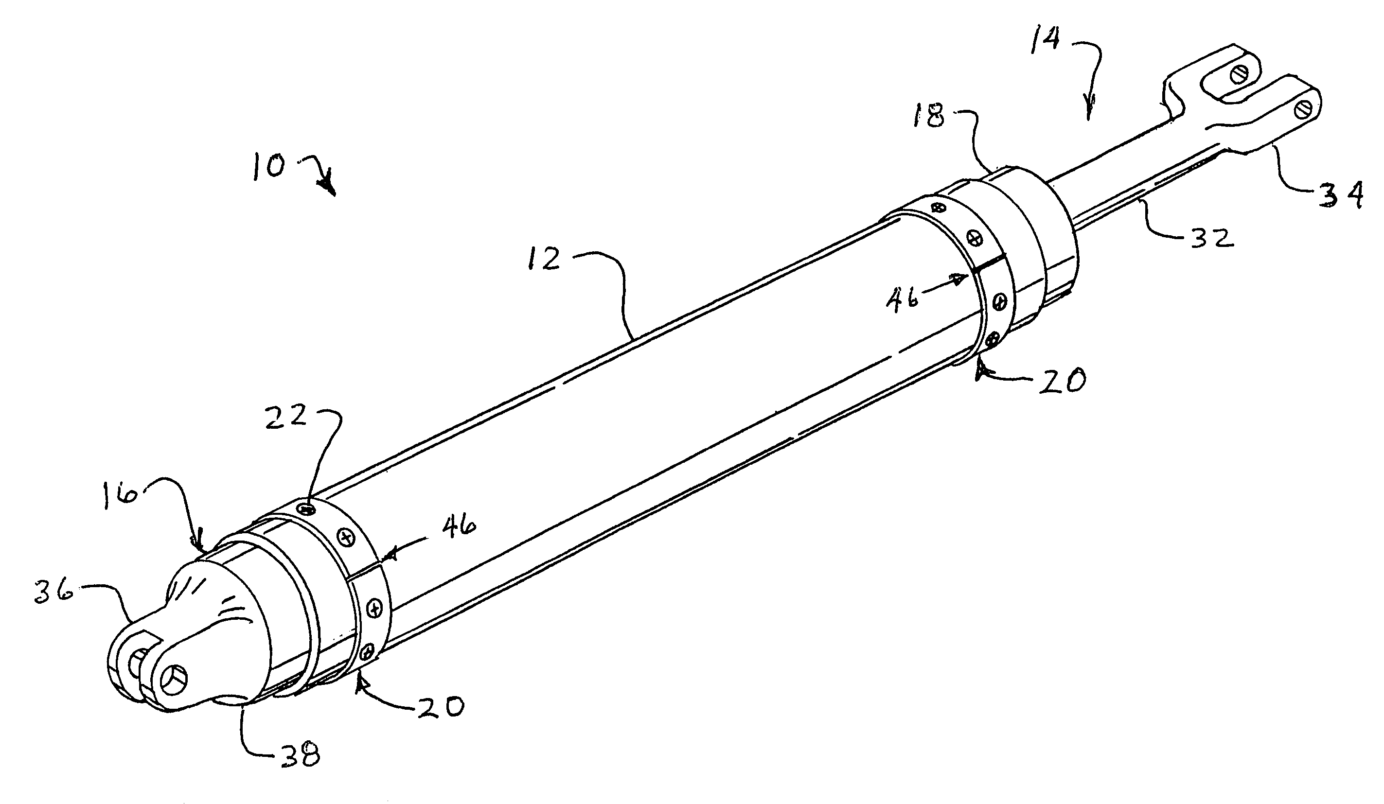
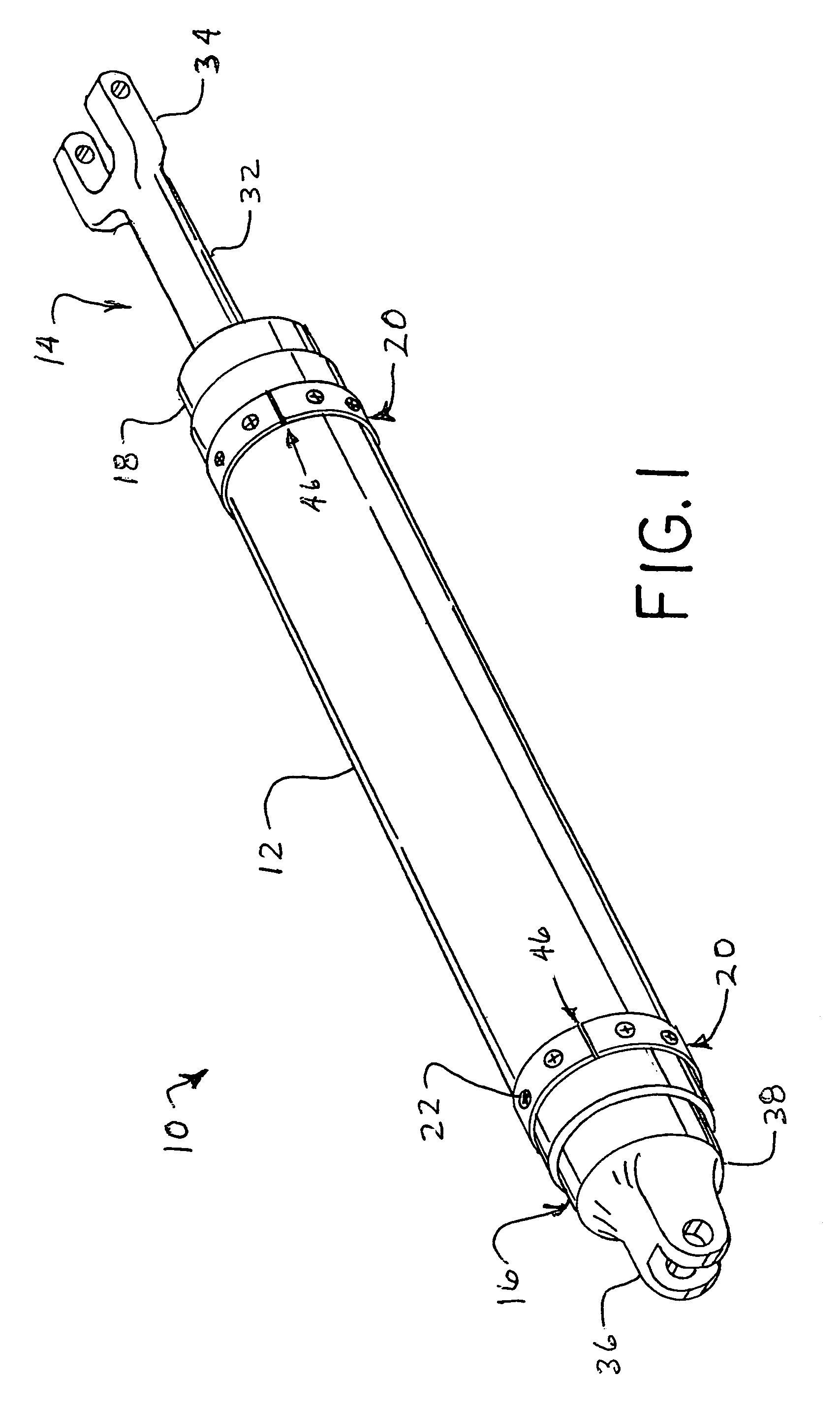
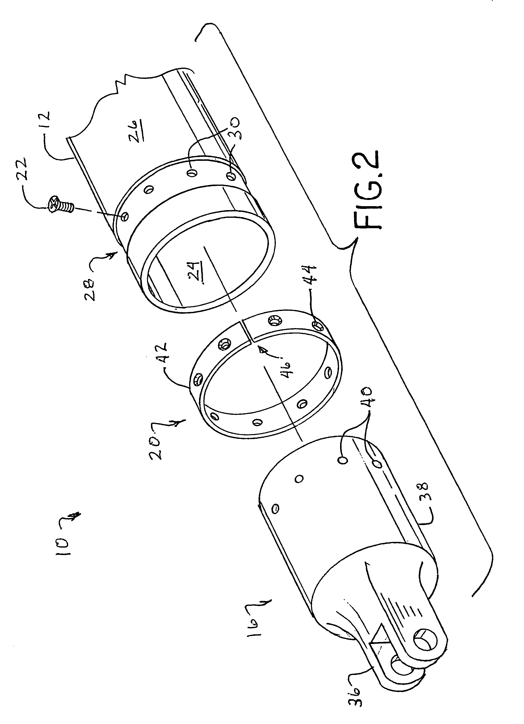
[0023]Referring now to the drawings, there is shown an embodiment of an end plug hydraulic / pneumatic assembly 10 of the present invention including a synthetic cylinder 12, a piston assembly 14, end plugs 16 and 18, split ring bands 20 and fasteners 22. End plugs 16 and 18 are inserted into cylinder 12 and are secured thereby by interaction of fasteners 22 going through openings in split ring bands 20 through cylinder 12 and into end plugs 16 and 18.

[0024]In the embodiment shown, synthetic cylinder 12 is in the form of a composite cylinder or tube made of a fiberglass matrix embedded within a resin, also known as a reinforced polymeric composite cylinder 12. Reinforced polymeric composite cylinder 12 may be a glass reinforced filament wound thermoset composite tube 12. Reinforced polymeric composite cylinder 12 includes an inner surface 24, an outer surface 26, annular grooves 28 and holes 30. Inner surface 24 is substantially smooth and cylindrical in nature, even though inner surf...


PUM


Abstract

A pressure assembly including a cylinder, an end plug and a split ring band. The cylinder has an end, an inner surface and an outer surface. The end plug is inserted into the end of the cylinder, the end plug having an outer surface that is in partial contact with the inner surface of the cylinder. The split ring band is in contact with the outer surface of the cylinder, the split ring band being secured to the cylinder and to the end plug.

Description

BACKGROUND OF THE INVENTION[0001]1. Field of the Invention[0002]The present invention relates to a hydraulic / pneumatic cylinder, and, more particularly, to a hydraulic / pneumatic reinforced polymeric composite cylinder with a removable end plug.[0003]2. Description of the Related Art[0004]Hydraulic and pneumatic cylinders are utilized for converting pressurized fluid into mechanical movement in a controlled manner. Hydraulics allow for the amplification of mechanical force by translating a pressure applied against a surface to force a piston to move inside of the cylinder, the piston being connected to a shaft that extends beyond the cylinder to thereby move a connected assembly. Air cylinders are often used in environments where hydraulic fluids would be undesirable, such as in food processing facilities.[0005]In a typical hydraulic / pneumatic cylinder, one end of the cylinder is enclosed with a plug and an opposite end is enclosed with a plug having a hole therein for accommodating ...

Claims


Application Information

Patent Timeline
Patent Type & Authority Patents(United States)
IPC IPC(8): F16J10/00
CPCF15B15/1438F16J10/00
Inventor FISH, ELSON B.
Owner POLYGON
Why Eureka
Try Eureka