Pressure regulated solenoid valve having integral mounting structure

a solenoid valve and mounting structure technology, applied in the direction of fluid pressure control, process and machine control, instruments, etc., can solve the problems of fluid leakage, time-consuming, and difficulty in forming connections

Inactive Publication Date: 2007-07-10
ROBERTSHAW CONTROLS CO
View PDF5 Cites 8 Cited by
  • Summary
  • Abstract
  • Description
  • Claims
  • Application Information

AI Technical Summary

Benefits of technology

[0006]In one aspect, the invention provides a regulator valve for managing a fluid in an appliance. The regulator valve comprises a housing having an inlet, an inlet filter section, a pressure regulation section, an outlet valving section, and an outlet in fluid communication therethrough. The housing further has a mounting structure including a mounting flange that has a locking tab depending therefrom. The filter is removably positioned in the inlet filter section of the housing for removing contaminants from the fluid. The pressure regulator is positioned in the pressure regulation section of the housing for regulating an outlet fluid pressure. The solenoid valve is positioned in the valving section of the housing for alternatively permitting expulsion of the fluid from the outlet and preventing expulsion of the fluid from the outlet.
[0011]The outlet valving section is sized to accommodate a solenoid valve that may be positioned thereon for alternatively permitting expulsion of the fluid from the outlet and preventing expulsion of the fluid from the outlet.

Problems solved by technology

Unfortunately, each of the components must be connected to a water source, to one of the other components, to a water delivery device (e.g., a bubbler), and the like, using a tube, a pipe, or some other type of conduit capable of distributing fluids.
Each connection can be difficult to form, time consuming, and a potential source of fluid leaks.
Undesirably, each device usually has its own unique type of fastener.
Therefore, securing the host of components to the appliance can be difficult, can require several different types of connections, and can be very time consuming.

Method used


Image

  • Pressure regulated solenoid valve having integral mounting structure
  • Pressure regulated solenoid valve having integral mounting structure
  • Pressure regulated solenoid valve having integral mounting structure

Examples


Embodiment Construction

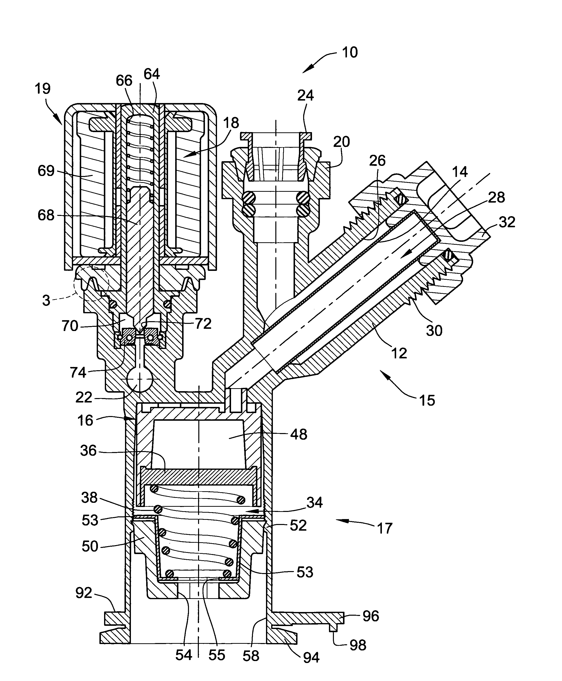
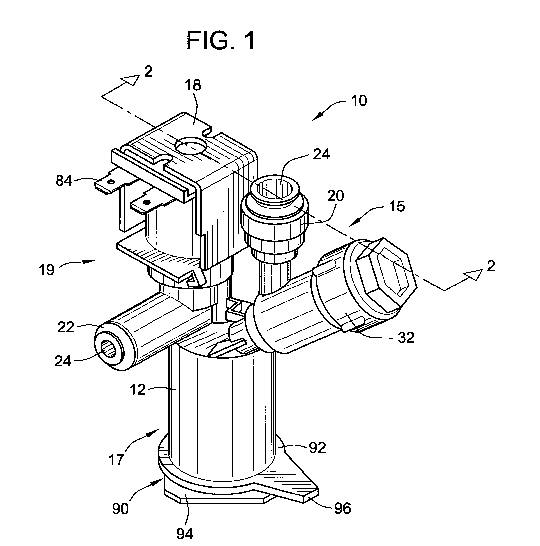
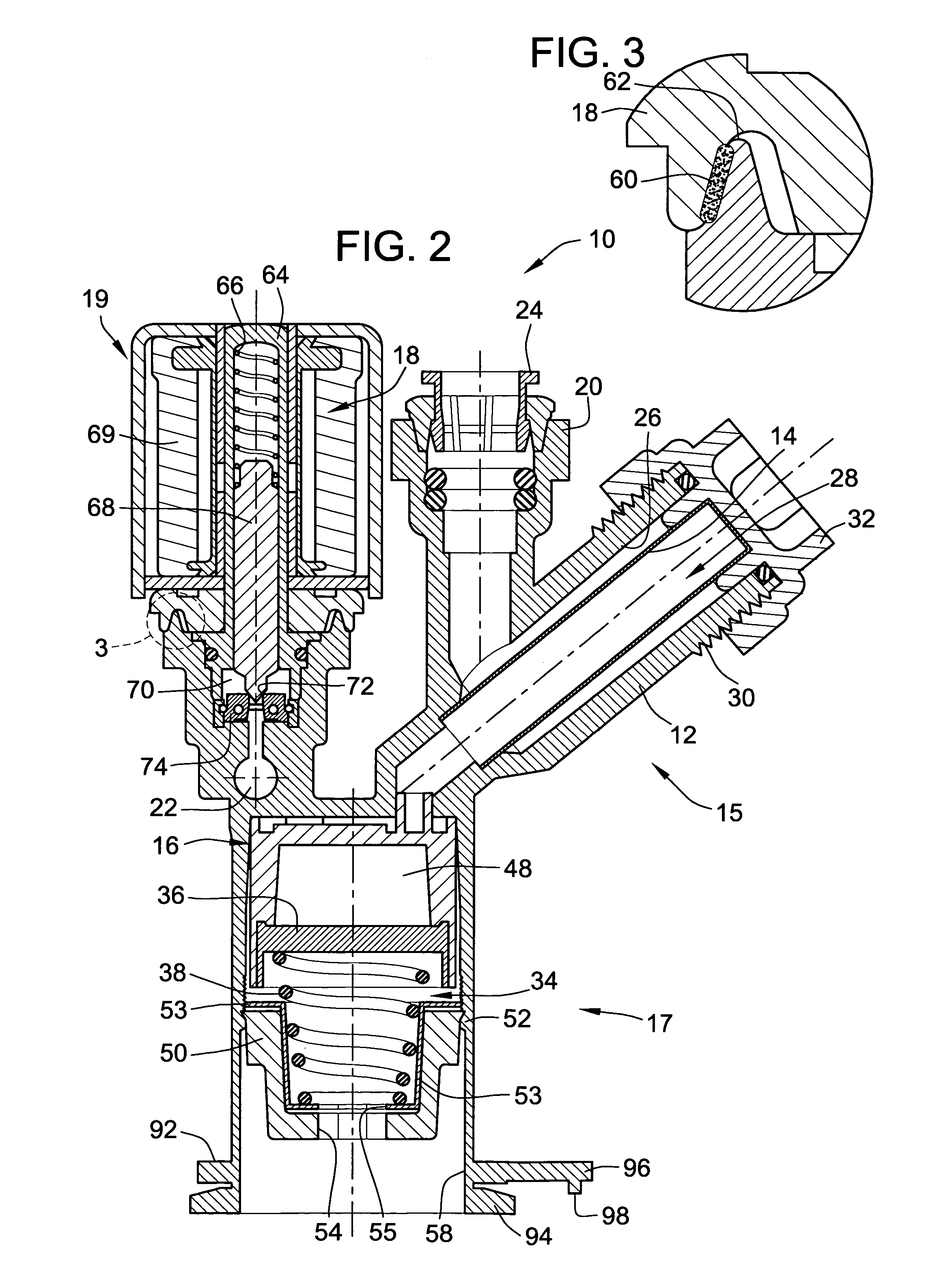
[0023]Referring to FIG. 1, an embodiment of a regulator valve 10 constructed in accordance with the teachings of the present invention is illustrated. The regulator valve 10 includes a housing 12 that contains a filter 14 (see FIG. 2) within inlet filter section 15, a pressure regulator 16 (see FIG. 2) within the body pressure regulation section 17, and a solenoid valve 18 within outlet valving section 19. The integration of the filter 14, the pressure regulator 16 and the solenoid valve 18 within housing 12 eliminates the mounting and plumbing requirements for each of these components such that the regulator valve 10 functions as a single, integral unit requiring only a single inlet connection and a single outlet connection. This eliminates or greatly reduces the chance of leakage, the time and expense of installing and plumbing each component in an appliance (e.g., a drinking fountain), and the time and trouble servicing these components.

[0024]The housing 12 includes a single inle...


PUM


Abstract

A regulator valve for managing a fluid in an appliance is provided. The regulator valve comprises a housing having an inlet and an outlet, a filter, a pressure regulator, a solenoid valve, a mounting structure, and a locking tab depending from the mounting structure. The inlet and outlet utilize quick connect adaptors. The pressure regulator maintains the fluid in the housing within a desired pressure range and the solenoid valve alternatively permits and prevents expulsion of the fluid from the outlet. The twist mount is inserted through a twist mount aperture on, e.g., a drinking fountain and rotated until a portion of the twist mount engages with a portion of the drinking fountain and the locking tab rests in a tab aperture on the drinking fountain. Therefore, the regulator valve is secured to the drinking fountain and can clean, regulate, and manage the fluid.

Description

FIELD OF THE INVENTION[0001]This invention relates generally to solenoid valves, pressure regulators, and filters used in appliances, such as drinking fountains, and methods of securing such components to the appliance.BACKGROUND OF THE INVENTION[0002]A typical appliance (e.g., a drinking fountain) can include various components such as a solenoid valve for controlling the expulsion of water from the fountain, a pressure regulator for maintaining the pressure of the water dispensed within a desired pressure range, and a filter for removing contaminants from the water.[0003]Unfortunately, each of the components must be connected to a water source, to one of the other components, to a water delivery device (e.g., a bubbler), and the like, using a tube, a pipe, or some other type of conduit capable of distributing fluids. Each connection can be difficult to form, time consuming, and a potential source of fluid leaks.[0004]Additionally, each of the components must be independently secur...

Claims


Application Information

Patent Timeline
Patent Type & Authority Patents(United States)
IPC IPC(8): F16K21/00
CPCF16K31/0655Y10T137/782Y10T137/8122Y10T137/87917
Inventor KNOP, DAVID G.
Owner ROBERTSHAW CONTROLS CO
Why Eureka
Try Eureka