

Method of operator presence control on walk behind powered equipment
Patent Information
- Authority / Receiving Office
- US · United States
- Patent Type
- Patents(United States)
- Current Assignee / Owner
- TEXTRON INNOVATIONS
- Publication Date
- 2007-07-10
Smart Images
Figure 1 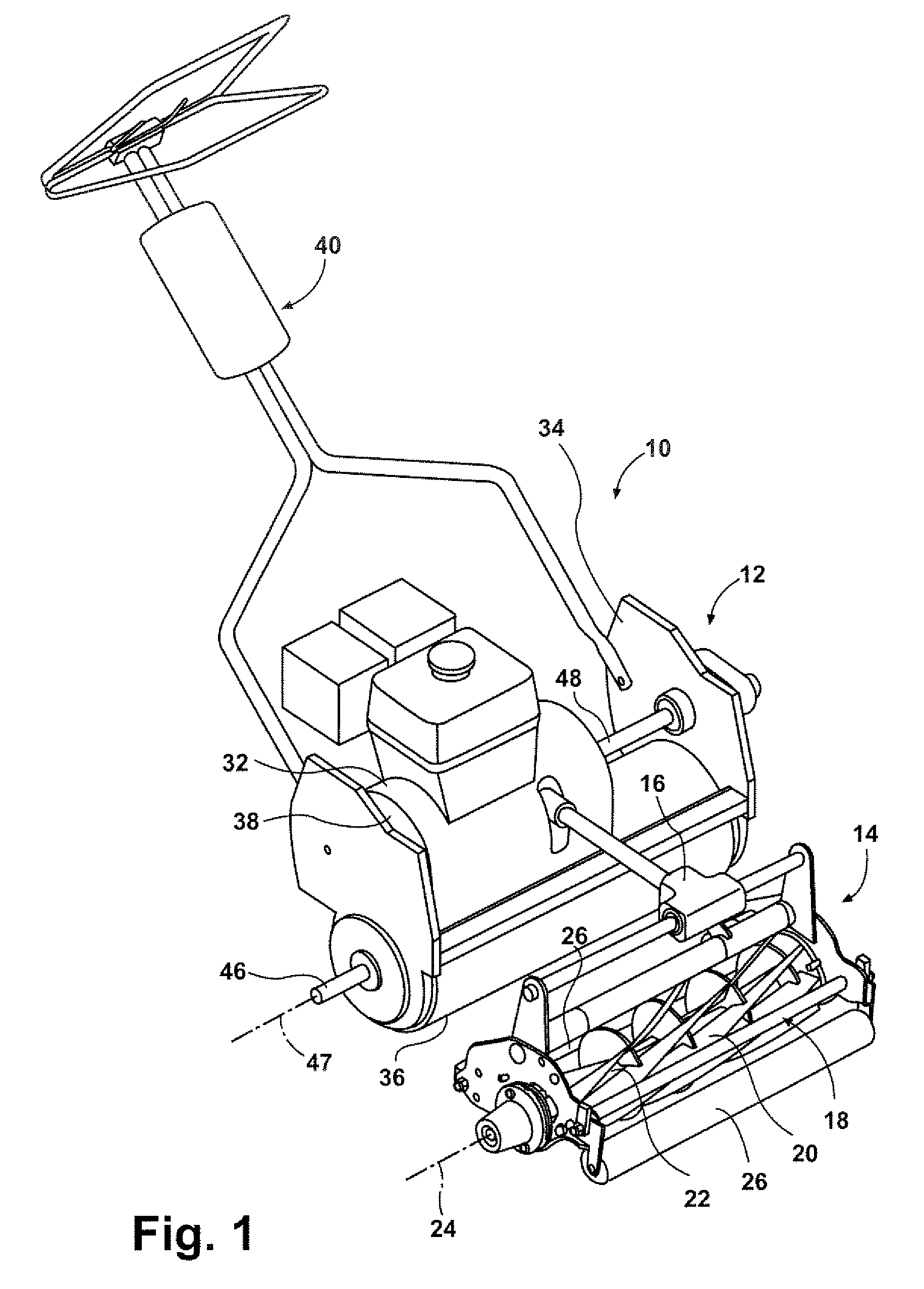
Figure 2 
Figure 3
Abstract
Description
FIELD OF THE INVENTION
[0001] The present invention relates to walk behind powered equipment and, more particularly, relates to a walk behind powered equipment having an improved operator presence system.BACKGROUND OF THE INVENTION
[0002] As is known in the art, walk behind powered equipment is often used in a wide variety of applications, such as lawn mowers, greens mowers, roto-tillers, aerators, snowblowers, and the like. Walk behind powered equipment typically includes an engine, either an internal combustion engine and / or electric motor, that is used to power a drive system and / or implement disengagement systems to propel the unit and operate the device, respectively. In the interest of safety, it is well known to use an operator presence system that must be triggered by an operator to ensure positive control of the powered equipment.
[0003] To this end, many known operator presence systems utilize a two stage detection system. For example, with regard to drive systems, a first stage...