Packaging and dispensing system for sandwich food products

a food product and packaging technology, applied in the field of food product packaging and dispensing systems, can solve the problems of inconvenient and uneconomical refrigeration, adversely affecting the taste and texture of sandwiches, inconvenient and uneconomical, etc., and achieve the effect of minimizing the possibility of contamination

Inactive Publication Date: 2007-07-10
GROSSMAN VICTOR A
View PDF49 Cites 33 Cited by
  • Summary
  • Abstract
  • Description
  • Claims
  • Application Information

AI Technical Summary

Benefits of technology

[0014]The present invention provides a packaging and dispensing system that overcomes the disadvantages of the prior art discussed above. The packaging and dispensing system comprises a sealed dispenser which keeps the food (hereinafter filler, sandwich contents or simply contents) contained therein fresh and which provides for easy application of the filler (without ut

Problems solved by technology

This moisture adversely affects the sandwiches' taste and texture.
Accordingly, when moist fillings such as egg salad or tuna salad are used, the sandwiches must be consumed within a relatively short period of time, which is inconvenient and uneconomical.
However, refrigeration at times may be inconvenient or unavailable.
Moreover, refrigeration adversely affects the taste of the bread and therefore may not be desirable or advantageous.
Although there are a number of prior art methods to deal with the aforementioned problems associated with sandwiches containing moist and/or sticky fillings, none of them provide for an easily-dispensed, sanitary, long-lasting, fresh-tasting sandwich.
Although this method does keep the bread from absorbing moisture from the filling, it requires that the user make the sandwich after unpacking the bread and unpacking the filler, which is inconvenient.
Additionally, the extra handling involved in making the sandwich increases the likelihood that the sandwich will become contaminated, and requires the use of utensils which may be unavailable.
Additionally, thi

Method used


Image

  • Packaging and dispensing system for sandwich food products
  • Packaging and dispensing system for sandwich food products
  • Packaging and dispensing system for sandwich food products

Examples


first embodiment

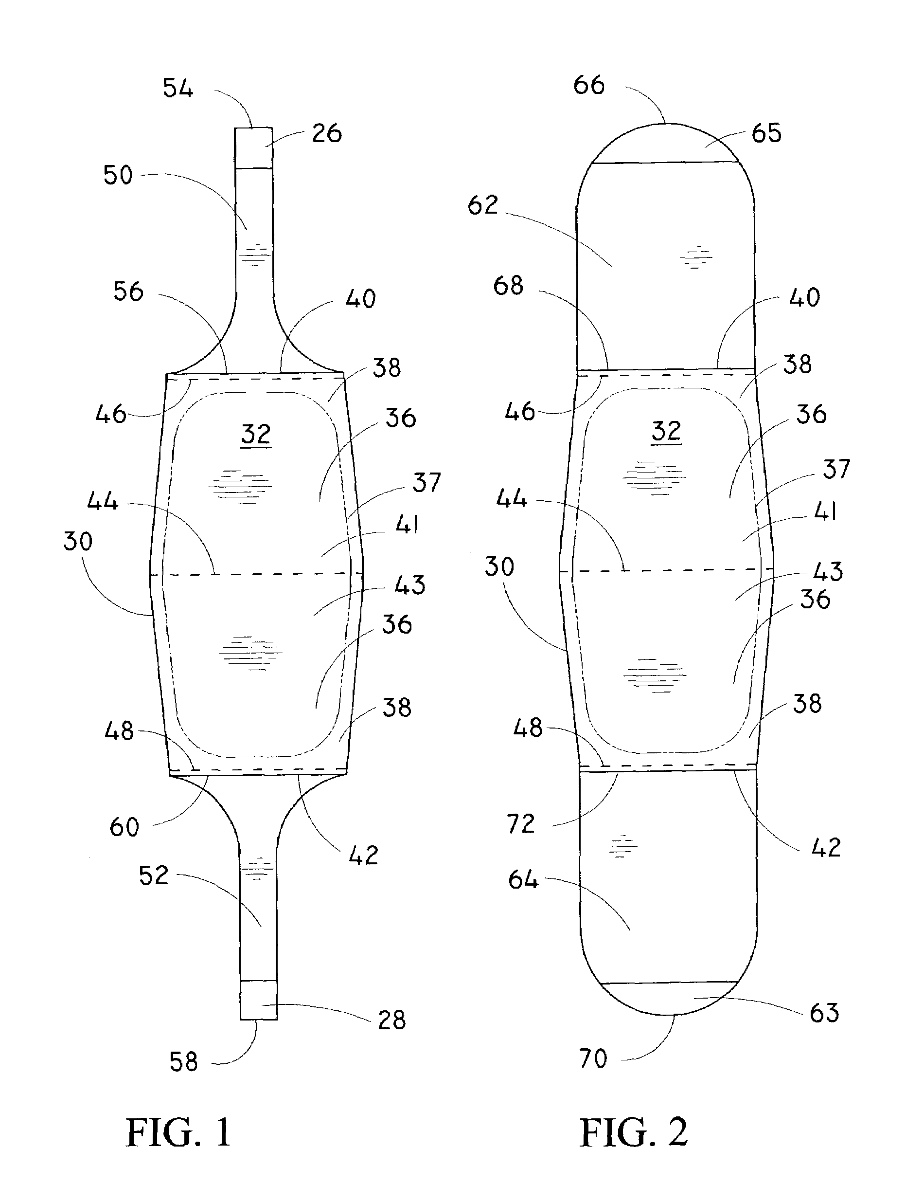
[0118]A top-view illustration of a single-piece outer cover and attached draw members according to the present invention is shown in FIG. 1. The outer cover 30 has an interior side 32 and an exterior side (not shown), an inner periphery 36 and an outer periphery 38, opposed first and second ends 40 and 42 respectively, mid fold 44, and folds 46 and 48. The inner periphery and outer periphery are separated by line 37. A removal means comprises two draw members, a first draw member 50, and a second draw member 52, both of which are attached to the outer cover 30. The first draw member 50 includes a first end 54, an opposed second end 56, and an optional first tab 26 which is located adjacent to the first end 54. The second end is attached to the first end of the outer cover adjacent to fold 46. Likewise, the second draw member includes a first end 58, an opposed second end 60, and an optional second tab 28 which is located adjacent to the first end, the second end being attached to th...

third embodiment

[0142]A side-view illustration of the inner container of the present invention having a single outer cover is shown in FIG. 6A. The inner container, generally referenced 150, is essentially similar to the inner container which is shown in FIG. 3 above and described in the corresponding text, with a difference being the inclusion of engaging tabs 152 which are attached to the side members 154 of the center member 156. Additionally, an optional weakened line 158 (e.g., a perforated or scored line), which runs transversely across the width of the outer cover 162 so that it extends to both side members, and is adjacent to the mid fold 160 of the outer cover, is included so the outer cover may be split or separated into two or more portions (e.g., a first sheet and a second sheet) if desired. A filler 166 is contained within the inner container.

[0143]A top-planar-view illustration of a third embodiment of the inner container of the present invention, as shown in FIG. 6A, having a single ...

fourth embodiment

[0144]A perspective-view illustration of the inner container of the present invention with a partial cutaway of the outer cover is shown in FIG. 7. The inner container, generally referenced 170, comprises a center member 172, an outer cover 176, a holding member 180, a first draw member 174, and a second draw member 178. The optional narrow-width draw members are shown for clarity, and in actual embodiments, it is preferred that full-width draw members be used. The outer periphery of the outer cover is releasably attached to the center member using a pressure-sensitive adhesive or other means (e.g., adhesives, thermal bonding, pressure bonding, a weakened line such as a perforated or scored line, etc.) as is known in the art. A flexible holding member is attached to the center member. In alternative embodiments, the holding member is formed integrally with the center member from the same sheet of material. In yet other alternative embodiments, the holding member is rigid. The holdin...


PUM

PropertyMeasurementUnit
Forceaaaaaaaaaa
Contentaaaaaaaaaa

Abstract

A sealed dispensing apparatus suitable for packaging and dispensing a single service portion of a food product. The food product is contained within an inner container cavity formed by an outer cover and a center member. Draw means are provided for transferring a force from the user to the outer cover, whereby the force peels the outer cover from the center section, thus folding the outer cover over itself as it is removed from the center section. The food product is dispensed when the inner container is opened by removing the outer cover from the center member. An optional outer container seals and holds portions of bread or other sandwich portions while the inner container is located therebetween. Box means holds the combination formed by the inner container and the outer container as well as optional condiments.

Description

FIELD OF THE INVENTION[0001]The present invention relates generally to packaging and dispensing systems for food products, and more particularly relates to a single-step apparatus for storing, handling, and dispensing individual sandwich-sized servings of food products, and a method for the same.BACKGROUND OF THE INVENTION[0002]There is currently an increasingly large consumer demand for low-cost sanitary foods which are packaged and ready-to-eat. A variety of techniques and materials have been used for packaging various types of food products in order to provide for their safe storage, shipping, and handling, as well as to provide for their easy consumption.[0003]One common type of ready-to-eat food is the sandwich (or sandwich-type foods such as hamburgers, hotdogs, pita-sandwiches, falafel sandwiches, gyros, subs, heros, tacos, burritos, etc., which will hereinafter be collectively referred to as sandwiches). Sandwiches find widespread use in fast-food-type operations. Additional...

Claims


Application Information

Patent Timeline
IPC IPC(8): A45C11/20
CPCA47G21/001Y10S206/804Y10S229/904Y10S229/902
Inventor GROSSMAN, VICTOR A.
Owner GROSSMAN VICTOR A
Why Eureka
Try Eureka